
Instruction Manual
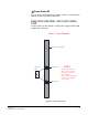
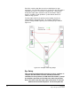
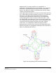
Table Of Contents
- The Eclipse Omega Matrix System: An Overview
- Operation
- The Eclipse Omega Matrix and Circuit Cards
- Front-Panel Controls and Lights
- Central Processor Unit (CPU) Card Description
- Analog Port Card Description
- Power Supply Description
- Connecting the Matrix
- Eclipse Fiber Linking
- Eclipse E-QUE Interface
- Eclipse IVC-32 Interface
- Eclipse LMC-64 Interface
- Installation
- Reconnecting the CPU Card’s Backup Battery
- Verifying the Shipment
- Unpacking the System
- Installing the Eclipse Omega Matrix
- Installing Power Supplies
- Installing the Rear RJ-45 Connector Panels
- Installing Rear RJ-45 Connector Panels in the Field
- Installing CPU Cards
- Installing Analog Port and Expansion Cards
- Wiring Audio Devices to the Matrix
- Wiring CPU Card Interfaces
- GPI/RLY Interface Connector
- RS-232 DB-9 Connector
- Alarm I/O Connector
- General-Purpose Outputs Connector (GP OUT)
- General-Purpose Inputs Connector (GP IN)
- Local Area Network Connectors (LAN1 and LAN2)
- E1/T1 Matrix to Matrix Crossover Cable
- E1/T1 Straight Cable Connections
- E1 to FreeSpeak/CellCom Antenna Pinout
- Maintenance
- Specifications
- Glossary
- Limited Warranty
- Technical Support & Repair Policy
Clear-Com
Eclipse Omega Instruction Manual
3-11
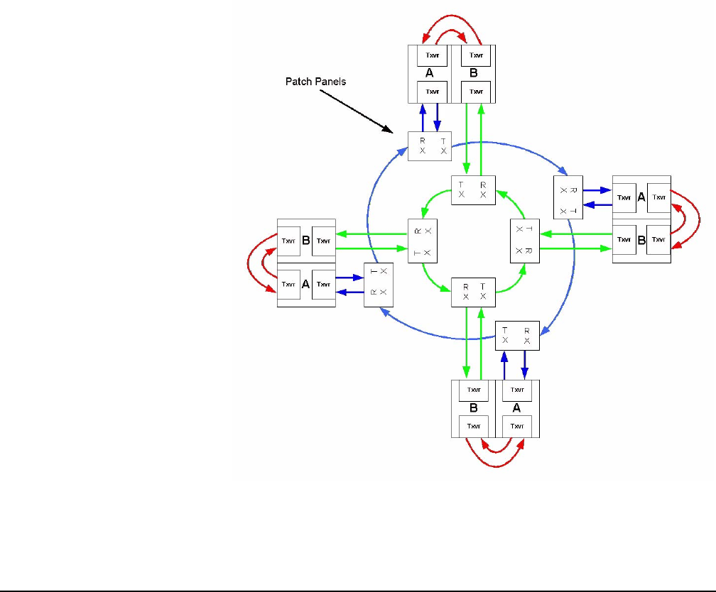
Switching to the secondary ring will cause audio breaks or
disturbances and temporary loss of crosspoint data. The self healing
mechanism is performed autonomously by the fiber Linking Card
whereas the switch-over between redundant cards and rings requires
software or operator intervention.
If two adjacent fiber connections are lost on one ring and the other ring
has a similar failure this will be handled as for the loss of a single node
where the nodes adjacent to the failed node will loop-back their
connections to the failed node healing the ring. The configuration
software will report the failure correctly as two failed cables . If two
non-adjacent fiber connections are lost on one ring and the other ring
has a similar fault the nodes adjacent to the failures will loop-back their
connections to the failed cables healing the ring into 2 separate
smaller rings. The configuration software will report the failure.
Note that in this instance the two sub-rings will be dependent on their
Ethernet connections for configuration and data transmission but there
will be no audio path between them.
Figure 3-5: Ring Topology Dual Card Set Redundancy