
Instruction Manual
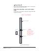
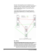
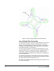
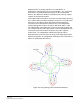

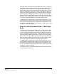
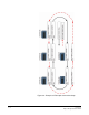
Table Of Contents
- The Eclipse Omega Matrix System: An Overview
- Operation
- The Eclipse Omega Matrix and Circuit Cards
- Front-Panel Controls and Lights
- Central Processor Unit (CPU) Card Description
- Analog Port Card Description
- Power Supply Description
- Connecting the Matrix
- Eclipse Fiber Linking
- Eclipse E-QUE Interface
- Eclipse IVC-32 Interface
- Eclipse LMC-64 Interface
- Installation
- Reconnecting the CPU Card’s Backup Battery
- Verifying the Shipment
- Unpacking the System
- Installing the Eclipse Omega Matrix
- Installing Power Supplies
- Installing the Rear RJ-45 Connector Panels
- Installing Rear RJ-45 Connector Panels in the Field
- Installing CPU Cards
- Installing Analog Port and Expansion Cards
- Wiring Audio Devices to the Matrix
- Wiring CPU Card Interfaces
- GPI/RLY Interface Connector
- RS-232 DB-9 Connector
- Alarm I/O Connector
- General-Purpose Outputs Connector (GP OUT)
- General-Purpose Inputs Connector (GP IN)
- Local Area Network Connectors (LAN1 and LAN2)
- E1/T1 Matrix to Matrix Crossover Cable
- E1/T1 Straight Cable Connections
- E1 to FreeSpeak/CellCom Antenna Pinout
- Maintenance
- Specifications
- Glossary
- Limited Warranty
- Technical Support & Repair Policy
Clear-Com
Eclipse Omega Instruction Manual
3-6
Each fiber card has two fiber transceivers with Duplex LC type
connectors. The TX1/RX1 connector is used for the main ring and the
TX2/RX2 connector is used for the secondary ring. Single mode
9/125µ fiber optic cable should be used for connections and the
matrices should be wired up with the system with the lowest I/P
address being system 1.
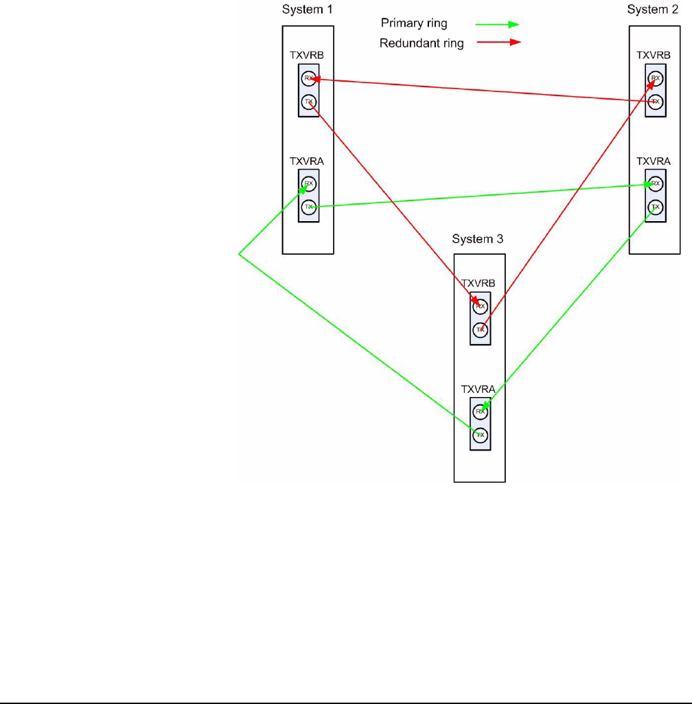
The fiber optic cable for the primary and secondary circuits are
plugged into the appropriate ports. An example showing three
systems configured with a primary and secondary ring is shown in
Figure 3-6.
Figure 3-3: Example Fiber Ring Setup
Eye Safety
This laser based single mode transceiver is a Class 1 product. It
complies with IEC 60825-1/A2:2001 and FDA performance
standards for laser products (21 CFR 1040.10 and 1040.11) except
for deviations pursuant to Laser Notice 50, dated July 26, 2001.
Note: The order of the fiber optic cable connections is reversed
between the front and rear panels. On the front panel the