
Instruction Manual
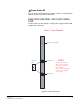
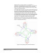
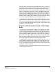
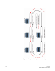
Table Of Contents
- The Eclipse Omega Matrix System: An Overview
- Operation
- The Eclipse Omega Matrix and Circuit Cards
- Front-Panel Controls and Lights
- Central Processor Unit (CPU) Card Description
- Analog Port Card Description
- Power Supply Description
- Connecting the Matrix
- Eclipse Fiber Linking
- Eclipse E-QUE Interface
- Eclipse IVC-32 Interface
- Eclipse LMC-64 Interface
- Installation
- Reconnecting the CPU Card’s Backup Battery
- Verifying the Shipment
- Unpacking the System
- Installing the Eclipse Omega Matrix
- Installing Power Supplies
- Installing the Rear RJ-45 Connector Panels
- Installing Rear RJ-45 Connector Panels in the Field
- Installing CPU Cards
- Installing Analog Port and Expansion Cards
- Wiring Audio Devices to the Matrix
- Wiring CPU Card Interfaces
- GPI/RLY Interface Connector
- RS-232 DB-9 Connector
- Alarm I/O Connector
- General-Purpose Outputs Connector (GP OUT)
- General-Purpose Inputs Connector (GP IN)
- Local Area Network Connectors (LAN1 and LAN2)
- E1/T1 Matrix to Matrix Crossover Cable
- E1/T1 Straight Cable Connections
- E1 to FreeSpeak/CellCom Antenna Pinout
- Maintenance
- Specifications
- Glossary
- Limited Warranty
- Technical Support & Repair Policy
Clear-Com
Eclipse Omega Instruction Manual
3-5
Frame Data LED
The red “status” light illuminates to indicate a failure in communication
between the fiber card and the CPU card.
FIBER CARD REAR PANEL LIGHTS AND CONNEC-
TIONS
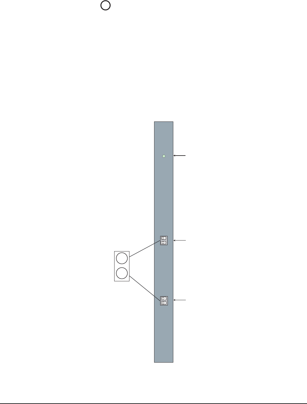
The fiber card rear card contains a single power supply indicator LED
and two fiber connectors.
Figure 3-2: Rear Fiber Card
6
+3.3V
When lit, +3.3 V power supply is on
TXVRB
TXVRA
Secondary Fiber Port
Primary Fiber Port
NOTE
Primary and Secondary
Fiber ports are reversed
with respect to the front
panel indicators.
Take care when unplugging
the cables to unplug the
correct cable.
Class 1 Laser Product
RX
TX
Transceiver
Lasers