
Instruction Manual

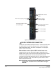


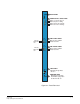
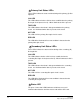
Table Of Contents
- The Eclipse Omega Matrix System: An Overview
- Operation
- The Eclipse Omega Matrix and Circuit Cards
- Front-Panel Controls and Lights
- Central Processor Unit (CPU) Card Description
- Analog Port Card Description
- Power Supply Description
- Connecting the Matrix
- Eclipse Fiber Linking
- Eclipse E-QUE Interface
- Eclipse IVC-32 Interface
- Eclipse LMC-64 Interface
- Installation
- Reconnecting the CPU Card’s Backup Battery
- Verifying the Shipment
- Unpacking the System
- Installing the Eclipse Omega Matrix
- Installing Power Supplies
- Installing the Rear RJ-45 Connector Panels
- Installing Rear RJ-45 Connector Panels in the Field
- Installing CPU Cards
- Installing Analog Port and Expansion Cards
- Wiring Audio Devices to the Matrix
- Wiring CPU Card Interfaces
- GPI/RLY Interface Connector
- RS-232 DB-9 Connector
- Alarm I/O Connector
- General-Purpose Outputs Connector (GP OUT)
- General-Purpose Inputs Connector (GP IN)
- Local Area Network Connectors (LAN1 and LAN2)
- E1/T1 Matrix to Matrix Crossover Cable
- E1/T1 Straight Cable Connections
- E1 to FreeSpeak/CellCom Antenna Pinout
- Maintenance
- Specifications
- Glossary
- Limited Warranty
- Technical Support & Repair Policy

Clear-Com
Eclipse Omega Instruction Manual
2-25
a corresponding rear-connector panel. Blank panels cover unused
slots.
Each port on the matrix can be located and identified by using the
rear-panel numbering grid.
• Columns 1 through 15 identify cards.
• Rows 1 through 16 identify ports on each card.
• Processor cards are designated P1 and P2.
A port can be identified precisely by identifying its card number and
port number on the card. For example, the ports on the first card are
designated 1-1, 1-2, 1-3, 1-4, and so on; the ports on the second
card are designated 2-1, 2-2, 2-3, 2-4, and so on.
Each rear connector panel associated with an E-QUE interface holds
eleven RJ-45 ports:
• Eight ports for connection to wireless equipment.
• Two ports for DECT sync.
• One port for LAN interface.
Each rear connector panel associated with an IVC-32 interface holds
eleven RJ-45 ports:
• Eight ports for connection to E1/T1 equipment (not used).
• Two ports for DECT sync (not used).
• One port for LAN interface used for IP-enabled V-Series panels and
Concert panels.
Each rear connector panel associated with an LMC-64 interface holds
eleven RJ-45 ports:
• Eight ports for connection to E1/T1 equipment (not used).
• Two ports for DECT sync (not used).
• One port for LAN interface used for broadcasting audio levels to
Production Maestro Pro clients.
Each rear connector panel associated with an E-FIB interface holds
two fiber ports (TXVRA and TXVRB).