
Instruction Manual

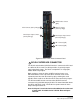


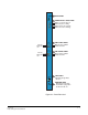
Table Of Contents
- The Eclipse Omega Matrix System: An Overview
- Operation
- The Eclipse Omega Matrix and Circuit Cards
- Front-Panel Controls and Lights
- Central Processor Unit (CPU) Card Description
- Analog Port Card Description
- Power Supply Description
- Connecting the Matrix
- Eclipse Fiber Linking
- Eclipse E-QUE Interface
- Eclipse IVC-32 Interface
- Eclipse LMC-64 Interface
- Installation
- Reconnecting the CPU Card’s Backup Battery
- Verifying the Shipment
- Unpacking the System
- Installing the Eclipse Omega Matrix
- Installing Power Supplies
- Installing the Rear RJ-45 Connector Panels
- Installing Rear RJ-45 Connector Panels in the Field
- Installing CPU Cards
- Installing Analog Port and Expansion Cards
- Wiring Audio Devices to the Matrix
- Wiring CPU Card Interfaces
- GPI/RLY Interface Connector
- RS-232 DB-9 Connector
- Alarm I/O Connector
- General-Purpose Outputs Connector (GP OUT)
- General-Purpose Inputs Connector (GP IN)
- Local Area Network Connectors (LAN1 and LAN2)
- E1/T1 Matrix to Matrix Crossover Cable
- E1/T1 Straight Cable Connections
- E1 to FreeSpeak/CellCom Antenna Pinout
- Maintenance
- Specifications
- Glossary
- Limited Warranty
- Technical Support & Repair Policy

Clear-Com
Eclipse Omega Instruction Manual
2-24
Note: A shielded cable should be used.
GENERAL-PURPOSE INPUTS CONNECTOR
(“GP IN”)
The female 25-pin D-type socket labeled “GP IN” connects the Eclipse
Omega CPU card to eight general purpose inputs (GPIs).
An external device such as an foot switch, a panel-mounted switch or
the logic output of some other device can be connected to the “GP IN”
connector. When the external device is activated, it sends a control
signal into the matrix to perform one of several preset functions, such
as turning an intercom panel’s microphone on or off, muting a
microphone’s output, or turning a panel’s speaker off. The function to
perform and the panel upon which it is performed is configured using
ECS.
Note: A shielded cable should be used.
LOCAL AREA NETWORK 1 PORT (“LAN 1”)
The RJ-45 socket labeled “LAN 1” connects a local area network
(LAN) to the CPU card through a standard Ethernet connection. The
green LED indicates the port is connected and the amber LED
indicates activity.
Note: If this port is used a ferrite must be added to the socket end
of each cable. A suitable ferrite is Würth Electronik part:
74271132.
Note: A shielded CAT-5 cable should be used.
LOCAL AREA NETWORK 2 PORT (“LAN 2”)
The RJ-45 socket labeled “LAN 2” connects a second local area
network (LAN) to the CPU card through a standard Ethernet
connection. The green LED indicates the port is connected and the
amber LED indicates activity.
Note: If this port is used a ferrite must be added to the socket end
of each cable. A suitable ferrite is Würth Electronik part:
74271132.
Note: A shielded CAT-5 cable should be used.
CONNECTING PORT CARDS
Each rear-connector panel associated with an MVX-A16 interface
holds the sixteen RJ-45 connectors that connect the matrix to intercom
panels and interfaces. Each front-installed MVX-A16 port card requires
5
6
7