
Instruction Manual
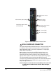


Table Of Contents
- The Eclipse Omega Matrix System: An Overview
- Operation
- The Eclipse Omega Matrix and Circuit Cards
- Front-Panel Controls and Lights
- Central Processor Unit (CPU) Card Description
- Analog Port Card Description
- Power Supply Description
- Connecting the Matrix
- Eclipse Fiber Linking
- Eclipse E-QUE Interface
- Eclipse IVC-32 Interface
- Eclipse LMC-64 Interface
- Installation
- Reconnecting the CPU Card’s Backup Battery
- Verifying the Shipment
- Unpacking the System
- Installing the Eclipse Omega Matrix
- Installing Power Supplies
- Installing the Rear RJ-45 Connector Panels
- Installing Rear RJ-45 Connector Panels in the Field
- Installing CPU Cards
- Installing Analog Port and Expansion Cards
- Wiring Audio Devices to the Matrix
- Wiring CPU Card Interfaces
- GPI/RLY Interface Connector
- RS-232 DB-9 Connector
- Alarm I/O Connector
- General-Purpose Outputs Connector (GP OUT)
- General-Purpose Inputs Connector (GP IN)
- Local Area Network Connectors (LAN1 and LAN2)
- E1/T1 Matrix to Matrix Crossover Cable
- E1/T1 Straight Cable Connections
- E1 to FreeSpeak/CellCom Antenna Pinout
- Maintenance
- Specifications
- Glossary
- Limited Warranty
- Technical Support & Repair Policy

Clear-Com
Eclipse Omega Instruction Manual
2-23
Note: A shielded cable should be used.
RS-232 CONNECTOR
The female 9-pin D-type socket labeled “RS-232” connects the CPU
card to an external computer.
Note: A shielded cable should be used.
ALARM I/O CONNECTOR
The female 9-pin D-type socket labeled “Alarm I/O” connects the
Eclipse matrix to an external alarm indicator, such as a light or buzzer
and/or to an external alarm source.
Note: A shielded cable should be used.
GENERAL-PURPOSE OUTPUTS CONNECTOR
(“GP OUT”)
The male 25-pin D-type socket labeled “GP OUT” connects the CPU
card to eight general purpose outputs (GPOs). General-purpose
outputs are single-pole double-throw relays with contact ratings of 30
VDC (volts direct current) at 1 ampere.
A general purpose output or “relay” is a switch that is controlled
remotely. The relay is programmed in ECS to close a contact
whenever an specified intercom panel key is pressed. When the
contact is closed, it completes an electronic circuit’s signal path so that
a remote device, such as a light, is powered.
A GPO can be programmed to mute a speaker, to turn on an applause
light, to turn on a door lock, or to perform a variety of other functions.
For example, to get the attention of a panel operator working in a
high-noise environment such as a control booth, a relay can be
programmed to switch on a light at the operator panel each time an
incoming call is received, to ensure that the call is not missed.
Note: If the GP-OUT port is used on an Omega matrix fitted with
XP power supplies (part 740101Z) the following filter must
be fitted between the PROC-RCC socket and the cable:
CINCH FA-25PS/1-LF 25W D-type in-line 1000pF filter
(UK supplier: Farnell 111-4108)
If the Omega matrix is equipped with Power-One power
supplies (part 720379Z) this filter should not be fitted. If this
filter is already fitted to an Omega matrix and the power
supplies are changed to Power-One units the filter must
be
removed before the matrix is powered up.
2
3
4