
Instruction Manual


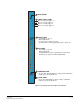

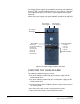

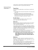

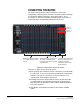
Table Of Contents
- The Eclipse Omega Matrix System: An Overview
- Operation
- The Eclipse Omega Matrix and Circuit Cards
- Front-Panel Controls and Lights
- Central Processor Unit (CPU) Card Description
- Analog Port Card Description
- Power Supply Description
- Connecting the Matrix
- Eclipse Fiber Linking
- Eclipse E-QUE Interface
- Eclipse IVC-32 Interface
- Eclipse LMC-64 Interface
- Installation
- Reconnecting the CPU Card’s Backup Battery
- Verifying the Shipment
- Unpacking the System
- Installing the Eclipse Omega Matrix
- Installing Power Supplies
- Installing the Rear RJ-45 Connector Panels
- Installing Rear RJ-45 Connector Panels in the Field
- Installing CPU Cards
- Installing Analog Port and Expansion Cards
- Wiring Audio Devices to the Matrix
- Wiring CPU Card Interfaces
- GPI/RLY Interface Connector
- RS-232 DB-9 Connector
- Alarm I/O Connector
- General-Purpose Outputs Connector (GP OUT)
- General-Purpose Inputs Connector (GP IN)
- Local Area Network Connectors (LAN1 and LAN2)
- E1/T1 Matrix to Matrix Crossover Cable
- E1/T1 Straight Cable Connections
- E1 to FreeSpeak/CellCom Antenna Pinout
- Maintenance
- Specifications
- Glossary
- Limited Warranty
- Technical Support & Repair Policy
Clear-Com
Eclipse Omega Instruction Manual
2-20
CONNECTING THE MATRIX
The Eclipse Omega matrix connects to devices such as the
configuration computer, panels, interfaces, and other matrices through
its rear-panel hardware connectors, often called “ports”. These
connectors are housed in modular removable panels. Each panel is
associated with a corresponding front-panel circuit card.
Figure 2-5: Eclipse Rear Connector Panels
There are six types of rear-connector panels:
• A CPU-card rear panel holds the various connectors associated with
the CPU card, such as the RS-232 connector for the configuration
computer. This panel’s connectors are discussed in the next
section, titled “Connecting the CPU Card”.
• An analog port-card rear panel holds the sixteen RJ-45 connectors
associated with its corresponding analog port-card front panel.
Intercom panels and interfaces connect to the matrix through this
rear-connector panel.
• An E-FIB fiber card provides two ports to connect fiber network
cables.
Port 1-1
Port 1-2
Port 1-3
Port 1-4
Blank panels are installed
in unused portions of the
frame.
Analog port rear panels have
16 RJ-45 connectors each,
to connect to intercom panels
and interfaces.
The CPU card rear panel
houses connectors for a
computer, network,
interfaces, alarms and
other matrices.