
Instruction Manual
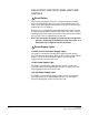
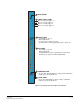
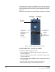
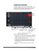
Table Of Contents
- The Eclipse Omega Matrix System: An Overview
- Operation
- The Eclipse Omega Matrix and Circuit Cards
- Front-Panel Controls and Lights
- Central Processor Unit (CPU) Card Description
- Analog Port Card Description
- Power Supply Description
- Connecting the Matrix
- Eclipse Fiber Linking
- Eclipse E-QUE Interface
- Eclipse IVC-32 Interface
- Eclipse LMC-64 Interface
- Installation
- Reconnecting the CPU Card’s Backup Battery
- Verifying the Shipment
- Unpacking the System
- Installing the Eclipse Omega Matrix
- Installing Power Supplies
- Installing the Rear RJ-45 Connector Panels
- Installing Rear RJ-45 Connector Panels in the Field
- Installing CPU Cards
- Installing Analog Port and Expansion Cards
- Wiring Audio Devices to the Matrix
- Wiring CPU Card Interfaces
- GPI/RLY Interface Connector
- RS-232 DB-9 Connector
- Alarm I/O Connector
- General-Purpose Outputs Connector (GP OUT)
- General-Purpose Inputs Connector (GP IN)
- Local Area Network Connectors (LAN1 and LAN2)
- E1/T1 Matrix to Matrix Crossover Cable
- E1/T1 Straight Cable Connections
- E1 to FreeSpeak/CellCom Antenna Pinout
- Maintenance
- Specifications
- Glossary
- Limited Warranty
- Technical Support & Repair Policy

Clear-Com
Eclipse Omega Instruction Manual
2-19
Note that the PSU2 fail light only works if the second power supply is
plugged into the matrix’s midplane from inside the matrix.
Note: A temperature sensor inside the power supply senses if the
power supply overheats, and switches on the second matrix
cooling fan. The red “Temp” light switches on to indicate
that the active CPU card, not a power supply, has
overheated.
Fan-On Indicator
Two fans deliver forced air cooling to the matrix’s power supplies. The
primary fan runs continuously. If a temperature exceeding a threshold
is detected in a power supply and extra cooling is required, a second
fan switches on to increase the air flow. The “fan-on” alarm light
illuminates red to indicate that the second fan is on.
POWER SUPPLY LIGHTS
The green power-supply lights illuminate to indicate that the power
supplies are receiving +12 V, –12 V, +5 V, and 3.3 V power.