
Instruction Manual
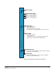
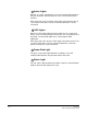
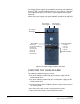
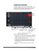
Table Of Contents
- The Eclipse Omega Matrix System: An Overview
- Operation
- The Eclipse Omega Matrix and Circuit Cards
- Front-Panel Controls and Lights
- Central Processor Unit (CPU) Card Description
- Analog Port Card Description
- Power Supply Description
- Connecting the Matrix
- Eclipse Fiber Linking
- Eclipse E-QUE Interface
- Eclipse IVC-32 Interface
- Eclipse LMC-64 Interface
- Installation
- Reconnecting the CPU Card’s Backup Battery
- Verifying the Shipment
- Unpacking the System
- Installing the Eclipse Omega Matrix
- Installing Power Supplies
- Installing the Rear RJ-45 Connector Panels
- Installing Rear RJ-45 Connector Panels in the Field
- Installing CPU Cards
- Installing Analog Port and Expansion Cards
- Wiring Audio Devices to the Matrix
- Wiring CPU Card Interfaces
- GPI/RLY Interface Connector
- RS-232 DB-9 Connector
- Alarm I/O Connector
- General-Purpose Outputs Connector (GP OUT)
- General-Purpose Inputs Connector (GP IN)
- Local Area Network Connectors (LAN1 and LAN2)
- E1/T1 Matrix to Matrix Crossover Cable
- E1/T1 Straight Cable Connections
- E1 to FreeSpeak/CellCom Antenna Pinout
- Maintenance
- Specifications
- Glossary
- Limited Warranty
- Technical Support & Repair Policy

Clear-Com
Eclipse Omega Instruction Manual
2-17
• If either of the matrix’s two cooling fans stop operating.
• If the temperature inside the Eclipse matrix exceeds a set threshold.
MAIN ALARM LIGHT
An alarm condition triggers the following events:
• The red main alarm light flashes.
• The matrix’s internal alarm buzzer sounds.
• Any installed alarm relay outputs switch to active (the normally open
contact closes and the normally closed contact opens). When the
alarm relay activates, it can cause an externally connected device
like a light or buzzer to switch on.
• One of the six auxiliary red alarm lights may go on to more precisely
indicate the source of the alarm condition. These lights are
discussed in further detail later in this section.
ALARM RESET BUTTON
When the alarm reset button is pressed the following events take
place, even if the alarm condition has not been corrected:
• The internal audible alarm buzzer stops buzzing.
• Any wired relay contacts return to their inactive state. If these relays
are connected to external alarm lights or alarm buzzers, those
lights or buzzers shut off.
If the original alarm condition still exists, the red main alarm light on the
matrix’s front panel continues to flash. The red main alarm light only
stops flashing when all original sources triggering the alarm are
corrected.
If a new alarm condition or conditions occur before the original alarm
conditions are corrected, the internal buzzer and relay contacts will not
reactivate. They will only reactivate after all original alarm conditions
are corrected.
AUXILIARY ALARM LIGHTS
When an alarm condition occurs, any of the six auxiliary alarm lights
may switch on, in addition to the main alarm light, to help diagnose the
alarm condition. The following sections describe the six auxiliary alarm
lights.
External Alarm (“Ext Alarm”)
The “external” alarm (labelled “EXT ALARM”) light switches on to
indicate that an alarm condition has triggered the built-in relay outputs
to turn on any externally installed alarms such as lights or bells. The