
Instruction Manual
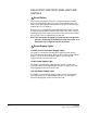
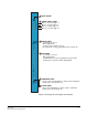
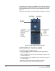
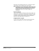
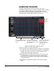
Table Of Contents
- The Eclipse Omega Matrix System: An Overview
- Operation
- The Eclipse Omega Matrix and Circuit Cards
- Front-Panel Controls and Lights
- Central Processor Unit (CPU) Card Description
- Analog Port Card Description
- Power Supply Description
- Connecting the Matrix
- Eclipse Fiber Linking
- Eclipse E-QUE Interface
- Eclipse IVC-32 Interface
- Eclipse LMC-64 Interface
- Installation
- Reconnecting the CPU Card’s Backup Battery
- Verifying the Shipment
- Unpacking the System
- Installing the Eclipse Omega Matrix
- Installing Power Supplies
- Installing the Rear RJ-45 Connector Panels
- Installing Rear RJ-45 Connector Panels in the Field
- Installing CPU Cards
- Installing Analog Port and Expansion Cards
- Wiring Audio Devices to the Matrix
- Wiring CPU Card Interfaces
- GPI/RLY Interface Connector
- RS-232 DB-9 Connector
- Alarm I/O Connector
- General-Purpose Outputs Connector (GP OUT)
- General-Purpose Inputs Connector (GP IN)
- Local Area Network Connectors (LAN1 and LAN2)
- E1/T1 Matrix to Matrix Crossover Cable
- E1/T1 Straight Cable Connections
- E1 to FreeSpeak/CellCom Antenna Pinout
- Maintenance
- Specifications
- Glossary
- Limited Warranty
- Technical Support & Repair Policy
Clear-Com
Eclipse Omega Instruction Manual
2-16
The XP type power supplies (part 740101Z) may need to be adjusted if
E-QUE, E-FIB, IVC-32 or LMC-64 interfaces are installed. For details
of the adjustments please refer to the system upgrade manual (part
810377Z).
Power-One power supply units (part 720379Z) should not be adjusted.
Figure 2-4: Power supply module’s front door
CONDITIONS THAT CAUSE AN ALARM
The following conditions trigger an alarm:
• If any of the voltages produced by the first power supply unit fall
below normal levels.
• If any of the voltages produced by the second power supply unit fall
below normal levels.
• If an internal matrix alarm condition activates a matrix relay to turn on
an external alarm.
• If the active CPU card exceeds a temperature threshold.
• If either of the CPU cards is removed from the matrix.
Power Supply LIghts
+12 Volt Light
+ 5 Volt Light
+3.3 Volt Light
--12 Volt Light
Alarm Lights
Main Alarm Light
External Alarm (EXT ALARM) Light
Temp Alarm Light
Fan-Fail Alarm Light
PSU1 Fail Light
PSU2 Fail Light
Fan-On Alarm Light
Alarm Reset Button
Euro Cassette
Power Supply 1
Euro Cassette
Power Supply 2
Euro Cassette
Alarm Lights