
Instruction Manual
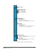
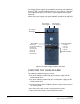
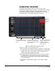
Table Of Contents
- The Eclipse Omega Matrix System: An Overview
- Operation
- The Eclipse Omega Matrix and Circuit Cards
- Front-Panel Controls and Lights
- Central Processor Unit (CPU) Card Description
- Analog Port Card Description
- Power Supply Description
- Connecting the Matrix
- Eclipse Fiber Linking
- Eclipse E-QUE Interface
- Eclipse IVC-32 Interface
- Eclipse LMC-64 Interface
- Installation
- Reconnecting the CPU Card’s Backup Battery
- Verifying the Shipment
- Unpacking the System
- Installing the Eclipse Omega Matrix
- Installing Power Supplies
- Installing the Rear RJ-45 Connector Panels
- Installing Rear RJ-45 Connector Panels in the Field
- Installing CPU Cards
- Installing Analog Port and Expansion Cards
- Wiring Audio Devices to the Matrix
- Wiring CPU Card Interfaces
- GPI/RLY Interface Connector
- RS-232 DB-9 Connector
- Alarm I/O Connector
- General-Purpose Outputs Connector (GP OUT)
- General-Purpose Inputs Connector (GP IN)
- Local Area Network Connectors (LAN1 and LAN2)
- E1/T1 Matrix to Matrix Crossover Cable
- E1/T1 Straight Cable Connections
- E1 to FreeSpeak/CellCom Antenna Pinout
- Maintenance
- Specifications
- Glossary
- Limited Warranty
- Technical Support & Repair Policy

Clear-Com
Eclipse Omega Instruction Manual
2-15
POWER SUPPLY DESCRIPTION
Eclipse Omega has two Euro Cassette power supply units that can be
easily installed or removed as needed. One power supply unit can
power an entire matrix; the second unit provides a backup in case of
an equipment failure.
In addition, the two supplies have separate IEC connectors to AC
mains power, and are designed for completely automatic and
transparent changeover between supplies in the event of an outage on
one of the AC mains circuits. For this feature to work, each power
supply should be connected to a different AC mains branch.
If the temperature inside the Eclipse matrix exceeds a threshold, both
an audible alarm and a warning light switch on, allowing the system
operator to diagnose and correct power anomalies while the system
remains in operation.
Warning: Eclipse Omega matrices may be fitted with XP (part
740101Z) or Power-One (part 720379Z) power supply
units depending on the date of manufacture. The
different types of power supply units must not be mixed
in an Omega matrix; if one of the pair of power supplies
is replaced it must be replaced with the same type of
power supply unit. If this is not possible both power
supplies must be replaced with power supply units of
the same type.
Power-One power supplies are identified by the part
number on the front of the unit; XP units do not have a
part number on the front of the unit.
Each cassette has two status lights located on the power supply unit in
the upper left corner. The green light stays on continuously to indicate
that the unit is receiving appropriate power. The amber (XP unit) or red
(Power-One) light goes on when a DC output or AC input falls too low.
DIAGNOSING POWER SUPPLY PROBLEMS
Figure 2-4 illustrates the front panel alarm lights, power supply lights,
and reset button. An alarm source triggers the main alarm light and
also one of the additional six red alarm lights, allowing the system
operator to identify or correct alarm conditions before they affect the
operation of the matrix.
Each of the four green power supply lights stays on continuously to
show that the power supplies are receiving sufficient AC current. When
one of these lights switches off, the power supplies need to be
replaced or repaired.
Under normal operating conditions, the red front-panel alarm lights
stay off, while the green power supply lights stay on continuously.