
Instruction Manual
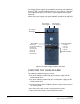
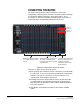
Table Of Contents
- The Eclipse Omega Matrix System: An Overview
- Operation
- The Eclipse Omega Matrix and Circuit Cards
- Front-Panel Controls and Lights
- Central Processor Unit (CPU) Card Description
- Analog Port Card Description
- Power Supply Description
- Connecting the Matrix
- Eclipse Fiber Linking
- Eclipse E-QUE Interface
- Eclipse IVC-32 Interface
- Eclipse LMC-64 Interface
- Installation
- Reconnecting the CPU Card’s Backup Battery
- Verifying the Shipment
- Unpacking the System
- Installing the Eclipse Omega Matrix
- Installing Power Supplies
- Installing the Rear RJ-45 Connector Panels
- Installing Rear RJ-45 Connector Panels in the Field
- Installing CPU Cards
- Installing Analog Port and Expansion Cards
- Wiring Audio Devices to the Matrix
- Wiring CPU Card Interfaces
- GPI/RLY Interface Connector
- RS-232 DB-9 Connector
- Alarm I/O Connector
- General-Purpose Outputs Connector (GP OUT)
- General-Purpose Inputs Connector (GP IN)
- Local Area Network Connectors (LAN1 and LAN2)
- E1/T1 Matrix to Matrix Crossover Cable
- E1/T1 Straight Cable Connections
- E1 to FreeSpeak/CellCom Antenna Pinout
- Maintenance
- Specifications
- Glossary
- Limited Warranty
- Technical Support & Repair Policy

Clear-Com
Eclipse Omega Instruction Manual
2-12
ANALOG PORT CARD FRONT-PANEL LIGHTS AND
CONTROLS
Reset Button
Pressing the reset button causes the card and all connected audio
devices to momentarily stop their current activity and to restart. The
card’s “frame data” light goes off when the reset starts and comes back
on when the reset is complete.
During the reset, configuration information downloads to the card and
its connected audio devices from the CPU card. If the entire system is
operating except for one port card, or one or more panels connected to
the card, press the reset button for that card only.
Note: The reset button is slightly recessed from the front panel to
prevent it from being accidentally pressed. A tool such as a
bent paper clip is required to press this button.
Power Supply Lights
+12-Volt and -12-Volt Power Supply Lights
The matrix’s +12-volt and -12-volt power supplies provide electric
current to these two green lights. When lit, these lights indicate that the
matrix’s +12-volt and -12-volt power supplies are present and
supplying electric current to the card.
+5-Volt Power Supply Light
The matrix’s +5-volt power supply provides electric current to this
green light. When lit, the light indicates that the +5 supply is present
and supplying electric current to the card.
+3.3-Volt Power Supply Light
The matrix’s +3.3-volt power supply provides electric current to this
green light. When lit, the light indicates that the +3.3-volt supply is
present and supplying electric current to the card.
1
2