
Instruction Manual

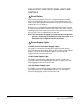
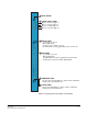
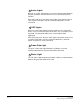
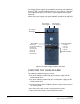

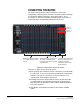
Table Of Contents
- The Eclipse Omega Matrix System: An Overview
- Operation
- The Eclipse Omega Matrix and Circuit Cards
- Front-Panel Controls and Lights
- Central Processor Unit (CPU) Card Description
- Analog Port Card Description
- Power Supply Description
- Connecting the Matrix
- Eclipse Fiber Linking
- Eclipse E-QUE Interface
- Eclipse IVC-32 Interface
- Eclipse LMC-64 Interface
- Installation
- Reconnecting the CPU Card’s Backup Battery
- Verifying the Shipment
- Unpacking the System
- Installing the Eclipse Omega Matrix
- Installing Power Supplies
- Installing the Rear RJ-45 Connector Panels
- Installing Rear RJ-45 Connector Panels in the Field
- Installing CPU Cards
- Installing Analog Port and Expansion Cards
- Wiring Audio Devices to the Matrix
- Wiring CPU Card Interfaces
- GPI/RLY Interface Connector
- RS-232 DB-9 Connector
- Alarm I/O Connector
- General-Purpose Outputs Connector (GP OUT)
- General-Purpose Inputs Connector (GP IN)
- Local Area Network Connectors (LAN1 and LAN2)
- E1/T1 Matrix to Matrix Crossover Cable
- E1/T1 Straight Cable Connections
- E1 to FreeSpeak/CellCom Antenna Pinout
- Maintenance
- Specifications
- Glossary
- Limited Warranty
- Technical Support & Repair Policy

Clear-Com
Eclipse Omega Instruction Manual
2-11
ANALOG PORT CARD DESCRIPTION
Analog port cards connect the central matrix to intercom panels and
interfaces. In a linked system, port cards connect trunk lines. The
analog card, designated the “MVX-A16”, supports normal audio feeds,
user panels, and trunk lines.
All cards contain a voice detection mechanism (“VOX”) that is
programmed from the ECS configuration software. VOX detection
allows a system operator to know when the audio on a particular
channel has exceeded a threshold. This is particularly useful for
channels that are inactive periodically, so that an operator is visually
cued when audio appears on the line.
Each analog port card has two system status lights. A port card’s
FRAME DATA light illuminates to indicate the card’s successful
communication with the CPU card. A port card’s STATUS light
illuminates to indicate a failure in communication between the port card
and the CPU card. When all port cards are lined up in the matrix, the
system status lights form a horizontal row showing the overall state of
the system.