
Instruction Manual
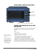
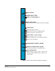
Table Of Contents
- The Eclipse Omega Matrix System: An Overview
- Operation
- The Eclipse Omega Matrix and Circuit Cards
- Front-Panel Controls and Lights
- Central Processor Unit (CPU) Card Description
- Analog Port Card Description
- Power Supply Description
- Connecting the Matrix
- Eclipse Fiber Linking
- Eclipse E-QUE Interface
- Eclipse IVC-32 Interface
- Eclipse LMC-64 Interface
- Installation
- Reconnecting the CPU Card’s Backup Battery
- Verifying the Shipment
- Unpacking the System
- Installing the Eclipse Omega Matrix
- Installing Power Supplies
- Installing the Rear RJ-45 Connector Panels
- Installing Rear RJ-45 Connector Panels in the Field
- Installing CPU Cards
- Installing Analog Port and Expansion Cards
- Wiring Audio Devices to the Matrix
- Wiring CPU Card Interfaces
- GPI/RLY Interface Connector
- RS-232 DB-9 Connector
- Alarm I/O Connector
- General-Purpose Outputs Connector (GP OUT)
- General-Purpose Inputs Connector (GP IN)
- Local Area Network Connectors (LAN1 and LAN2)
- E1/T1 Matrix to Matrix Crossover Cable
- E1/T1 Straight Cable Connections
- E1 to FreeSpeak/CellCom Antenna Pinout
- Maintenance
- Specifications
- Glossary
- Limited Warranty
- Technical Support & Repair Policy

Clear-Com
Eclipse Omega Instruction Manual
2-10
• Eclipse IP address - IP address of the LAN 1 port. Example output
- "IP 169.254.000.100". If this address isn't statically allocated, but
instead was allocated via DHCP server this will be pre-pended by
"DHCP ENABLED".
• System Number - This is only output if the rack is part of a linked
set. It is the system number of the node within the linked set.
Example output - "SYSTEM 3"
• Software version Number - Version number of the config card
software. Example output - "RACK 1.0.2.1"
• Hardware Serial number - Example output- "SERIAL 2251" in the
case where the HW serial number is 2251.
Full Reset Button
When a full reset is performed, all cards in the matrix reset regardless
of any system preferences in the program software and non-volatile
memory is cleared.
To perform a full reset:
1. Press and hold the card’s lower RESET button (the “full reset”
button).
2. Simultaneously press and release the card’s upper RESET button.
3. Continue holding the card’s lower RESET button for two seconds.
The card performs a full reset.
The same configuration that was active before the system was reset
will be active after reset.
When the cards and connected audio devices reset, they momentarily
stop their current activity and restart. During this process configuration
information is downloaded to the cards and audio devices from the
CPU card’s non-volatile RAM.
Note: Under normal operating conditions it is not necessary to
perform a full reset. Technical personnel might perform a
full reset if they believe that the CPU card is operating
incorrectly as a result of corruption of the microprocessor’s
internal data or instruction sequence.
7