
Instruction Manual
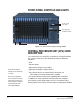
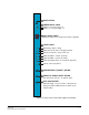
Table Of Contents
- The Eclipse Omega Matrix System: An Overview
- Operation
- The Eclipse Omega Matrix and Circuit Cards
- Front-Panel Controls and Lights
- Central Processor Unit (CPU) Card Description
- Analog Port Card Description
- Power Supply Description
- Connecting the Matrix
- Eclipse Fiber Linking
- Eclipse E-QUE Interface
- Eclipse IVC-32 Interface
- Eclipse LMC-64 Interface
- Installation
- Reconnecting the CPU Card’s Backup Battery
- Verifying the Shipment
- Unpacking the System
- Installing the Eclipse Omega Matrix
- Installing Power Supplies
- Installing the Rear RJ-45 Connector Panels
- Installing Rear RJ-45 Connector Panels in the Field
- Installing CPU Cards
- Installing Analog Port and Expansion Cards
- Wiring Audio Devices to the Matrix
- Wiring CPU Card Interfaces
- GPI/RLY Interface Connector
- RS-232 DB-9 Connector
- Alarm I/O Connector
- General-Purpose Outputs Connector (GP OUT)
- General-Purpose Inputs Connector (GP IN)
- Local Area Network Connectors (LAN1 and LAN2)
- E1/T1 Matrix to Matrix Crossover Cable
- E1/T1 Straight Cable Connections
- E1 to FreeSpeak/CellCom Antenna Pinout
- Maintenance
- Specifications
- Glossary
- Limited Warranty
- Technical Support & Repair Policy

Clear-Com
Eclipse Omega Instruction Manual
2-9
Each time the button is subsequently pressed the next configuration
number in the series appears in the dot-matrix display. The numbers
cycle forward until all of the choices have been displayed, then start
again at “1”.
When a non-active configuration’s number appears in the display, it
flashes to indicate its non-active status. When an active configuration’s
number (either 1,2, 3, or 4) appears in the display, it illuminates solidly
(without flashing) to indicate that it is the active configuration.
To select one of the four configurations from the CPU card
1. Repeatedly press the CONFIG button until the desired
configuration’s number (1,2,3, or 4) appears in the display.
2. When the desired number appears, press and hold the CONFIG
button until the display stops flashing. This should take about three
seconds.
The selected configuration then becomes the system’s active
operational configuration.
Engineering “ENG” Button
This button is used to reset the system to the default IP address
(169.254.0.100) with DHCP enabled and to display system information
on the LED dot matrix.
To perform an IP address reset sequence:
1. Press and hold the ‘ENG’ and ‘FULL RESET’ front panel buttons
simultaneously.
2. Press the ‘RESET’ button. If the system has two CPU cards (master
and slave) ensure that the IP address reset is performed on each
card as detailed below.
• Remove the slave CPU card if present.
• Press and hold the ‘ENG’ and ‘FULL RESET’ front panel buttons
simultaneously then press the ‘RESET’ button on the master CPU
card.
• Replace the slave CPU card if there is one otherwise the
procedure is complete.
• Remove the master CPU card.
• Press and hold the ‘ENG’ and ‘FULL RESET’ front panel buttons
simultaneously then press the ‘RESET’ button on the slave CPU
card.
• Replace the master CPU card.
System Status
If the “ENG” button only on the master CPU is pressed the following
system information will be displayed on the LED matrix:
• Eclipse release - "V5.2" at 5.2
6