
Instruction Manual
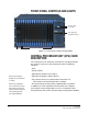
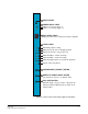
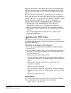
Table Of Contents
- The Eclipse Omega Matrix System: An Overview
- Operation
- The Eclipse Omega Matrix and Circuit Cards
- Front-Panel Controls and Lights
- Central Processor Unit (CPU) Card Description
- Analog Port Card Description
- Power Supply Description
- Connecting the Matrix
- Eclipse Fiber Linking
- Eclipse E-QUE Interface
- Eclipse IVC-32 Interface
- Eclipse LMC-64 Interface
- Installation
- Reconnecting the CPU Card’s Backup Battery
- Verifying the Shipment
- Unpacking the System
- Installing the Eclipse Omega Matrix
- Installing Power Supplies
- Installing the Rear RJ-45 Connector Panels
- Installing Rear RJ-45 Connector Panels in the Field
- Installing CPU Cards
- Installing Analog Port and Expansion Cards
- Wiring Audio Devices to the Matrix
- Wiring CPU Card Interfaces
- GPI/RLY Interface Connector
- RS-232 DB-9 Connector
- Alarm I/O Connector
- General-Purpose Outputs Connector (GP OUT)
- General-Purpose Inputs Connector (GP IN)
- Local Area Network Connectors (LAN1 and LAN2)
- E1/T1 Matrix to Matrix Crossover Cable
- E1/T1 Straight Cable Connections
- E1 to FreeSpeak/CellCom Antenna Pinout
- Maintenance
- Specifications
- Glossary
- Limited Warranty
- Technical Support & Repair Policy
Clear-Com
Eclipse Omega Instruction Manual
2-2
FRONT-PANEL CONTROLS AND LIGHTS
Figure 2-1: Front Panel of Eclipse Omega Matrix
CENTRAL PROCESSOR UNIT (CPU) CARD
DESCRIPTION
The central processor unit (CPU) card holds the circuitry that allows
the system to connect to, and communicate with, the following
interfaces:
• A PC
• External alarms
• Eight general-purpose inputs (GPIs)
• Eight general-purpose outputs (GPOs)
• Two separate local area network (LAN) connections for
Ethernet-based communication with a network
• An external interface that provides additional GPIs and GPOs
In addition, the card’s operational memory holds four complete
preassigned system configurations to access and activate either
directly from the CPU card or from the Eclipse Configuration Software.
CPU Cards
P1 & P2
Expansion Cards 1 through 15
Two Euro Cassette
Power Supplies
Power Supply Lights
and Alarm Reset Button
Note: General Purpose
Outputs are also referred to
as “relays”.
Note: If the configuration
does not remain in memory
after power off, please see
the first section in Chapter 3,
“Reconnecting the CPU
Card’s Backup Battery.