
Instruction Manual
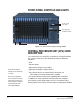


Table Of Contents
- The Eclipse Omega Matrix System: An Overview
- Operation
- The Eclipse Omega Matrix and Circuit Cards
- Front-Panel Controls and Lights
- Central Processor Unit (CPU) Card Description
- Analog Port Card Description
- Power Supply Description
- Connecting the Matrix
- Eclipse Fiber Linking
- Eclipse E-QUE Interface
- Eclipse IVC-32 Interface
- Eclipse LMC-64 Interface
- Installation
- Reconnecting the CPU Card’s Backup Battery
- Verifying the Shipment
- Unpacking the System
- Installing the Eclipse Omega Matrix
- Installing Power Supplies
- Installing the Rear RJ-45 Connector Panels
- Installing Rear RJ-45 Connector Panels in the Field
- Installing CPU Cards
- Installing Analog Port and Expansion Cards
- Wiring Audio Devices to the Matrix
- Wiring CPU Card Interfaces
- GPI/RLY Interface Connector
- RS-232 DB-9 Connector
- Alarm I/O Connector
- General-Purpose Outputs Connector (GP OUT)
- General-Purpose Inputs Connector (GP IN)
- Local Area Network Connectors (LAN1 and LAN2)
- E1/T1 Matrix to Matrix Crossover Cable
- E1/T1 Straight Cable Connections
- E1 to FreeSpeak/CellCom Antenna Pinout
- Maintenance
- Specifications
- Glossary
- Limited Warranty
- Technical Support & Repair Policy

Clear-Com
Eclipse Omega Instruction Manual
2-1
OPERATION
THE ECLIPSE OMEGA MATRIX AND CIRCUIT
CARDS
The Eclipse Omega matrix chassis houses the circuit cards, power
supplies, and connectors that form the central hardware of the system.
Measuring 19-inches wide and 6 rack units high (48.3 cm x 26.9 cm),
the matrix chassis installs in a standard equipment rack.
Various types of Eclipse Omega circuit cards perform unique
functions. System cards control overall system operation, analog
interfaces control the operation of connected panels and interfaces
and communications interfaces allow communication with wireless
equipment, fiber optic links and IP networks.
Two Euro Cassette power supplies provide fail-safe redundancy in the
event of a component failure or an AC circuit outage. Front-panel lights
give information about the condition of the power supplies, allowing the
system operator to take preventative corrective action.
Each MVX-A16 interface connects to an individual panel on the back
of the Eclipse Omega matrix. This panel holds the RJ-45 sockets for
connecting to intercom panels and interface modules.
The Eclipse Omega matrix is completely modular, allowing cards,
power supplies, and connector panels to be added or removed to meet
operational needs.
2