
Instruction Manual
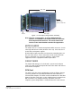


Table Of Contents
- The Eclipse Omega Matrix System: An Overview
- Operation
- The Eclipse Omega Matrix and Circuit Cards
- Front-Panel Controls and Lights
- Central Processor Unit (CPU) Card Description
- Analog Port Card Description
- Power Supply Description
- Connecting the Matrix
- Eclipse Fiber Linking
- Eclipse E-QUE Interface
- Eclipse IVC-32 Interface
- Eclipse LMC-64 Interface
- Installation
- Reconnecting the CPU Card’s Backup Battery
- Verifying the Shipment
- Unpacking the System
- Installing the Eclipse Omega Matrix
- Installing Power Supplies
- Installing the Rear RJ-45 Connector Panels
- Installing Rear RJ-45 Connector Panels in the Field
- Installing CPU Cards
- Installing Analog Port and Expansion Cards
- Wiring Audio Devices to the Matrix
- Wiring CPU Card Interfaces
- GPI/RLY Interface Connector
- RS-232 DB-9 Connector
- Alarm I/O Connector
- General-Purpose Outputs Connector (GP OUT)
- General-Purpose Inputs Connector (GP IN)
- Local Area Network Connectors (LAN1 and LAN2)
- E1/T1 Matrix to Matrix Crossover Cable
- E1/T1 Straight Cable Connections
- E1 to FreeSpeak/CellCom Antenna Pinout
- Maintenance
- Specifications
- Glossary
- Limited Warranty
- Technical Support & Repair Policy

Clear-Com
Eclipse Omega Instruction Manual
1-5
Each E-QUE front card has status LEDs for power, port activity and
LAN status. The port activity LEDs indicate whether there is a device
connected to an E1 port and that a connection has been established
between this port and the connected device.
The E-QUE interfaces must be fitted in the rightmost available slots
(furthest away from the CPU cards) on the Omega and up to four
E-QUE interfaces can be fitted on a matrix.
New functionality for E-QUE interfaces has been added in the Eclipse
software from release version 5.0. The new functionality provides E1
and T1 trunking, and E1 audio tie-lines to a 4000 system (as described
in chapter 4 of this manual).
IVC-32 IP Interface
The IVC-32 interface allows the Eclipse matrix to connect to IP
enabled V-Series panels and Concert users via an IP network.
Each IVC-32 interface consists of a front card with a reset button and
various status indicators, and a rear card with eleven RJ45 ports giving
eight E1/T1 ports (not used), DECT sync in and out (not used) and a
LAN port for IP connectivity.
Each IVC-32 front card has status LEDs for power, port activity and
LAN status.
The LAN indicators show whether there is a LAN connection and the
IP activity on the LAN port.
The IVC-32 cards must be fitted in the rightmost available slots
(furthest away from the CPU cards) on the Omega and up to four
IVC-32 interfaces can be fitted to a matrix.
LMC-64 Interface
The LMC-64 interface allows the Eclipse matrix to provide Production
Maestro Pro clients with audio level metering of Party Lines
(Conferences) and 4-Wire ports via an IP network.
Each LMC-64 interface consists of a front card with a reset button and
various status indicators, and a rear card with eleven RJ45 ports giving
eight E1/T1 ports (not used), DECT sync in and out (not used) and a
LAN port for IP connectivity.
Each LMC-64 front card has status LEDs for power, port activity and
LAN status.
The LAN indicators show whether there is a LAN connection and the
IP activity on the LAN port.
The LMC-64 cards must be fitted in the rightmost available slots
(furthest away from the CPU cards) on the Omega and up to four
LMC-64 interfaces can be fitted to a matrix.