
Instruction Manual
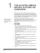
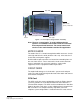


Table Of Contents
- The Eclipse Omega Matrix System: An Overview
- Operation
- The Eclipse Omega Matrix and Circuit Cards
- Front-Panel Controls and Lights
- Central Processor Unit (CPU) Card Description
- Analog Port Card Description
- Power Supply Description
- Connecting the Matrix
- Eclipse Fiber Linking
- Eclipse E-QUE Interface
- Eclipse IVC-32 Interface
- Eclipse LMC-64 Interface
- Installation
- Reconnecting the CPU Card’s Backup Battery
- Verifying the Shipment
- Unpacking the System
- Installing the Eclipse Omega Matrix
- Installing Power Supplies
- Installing the Rear RJ-45 Connector Panels
- Installing Rear RJ-45 Connector Panels in the Field
- Installing CPU Cards
- Installing Analog Port and Expansion Cards
- Wiring Audio Devices to the Matrix
- Wiring CPU Card Interfaces
- GPI/RLY Interface Connector
- RS-232 DB-9 Connector
- Alarm I/O Connector
- General-Purpose Outputs Connector (GP OUT)
- General-Purpose Inputs Connector (GP IN)
- Local Area Network Connectors (LAN1 and LAN2)
- E1/T1 Matrix to Matrix Crossover Cable
- E1/T1 Straight Cable Connections
- E1 to FreeSpeak/CellCom Antenna Pinout
- Maintenance
- Specifications
- Glossary
- Limited Warranty
- Technical Support & Repair Policy
Clear-Com
Eclipse Omega Instruction Manual
1-3
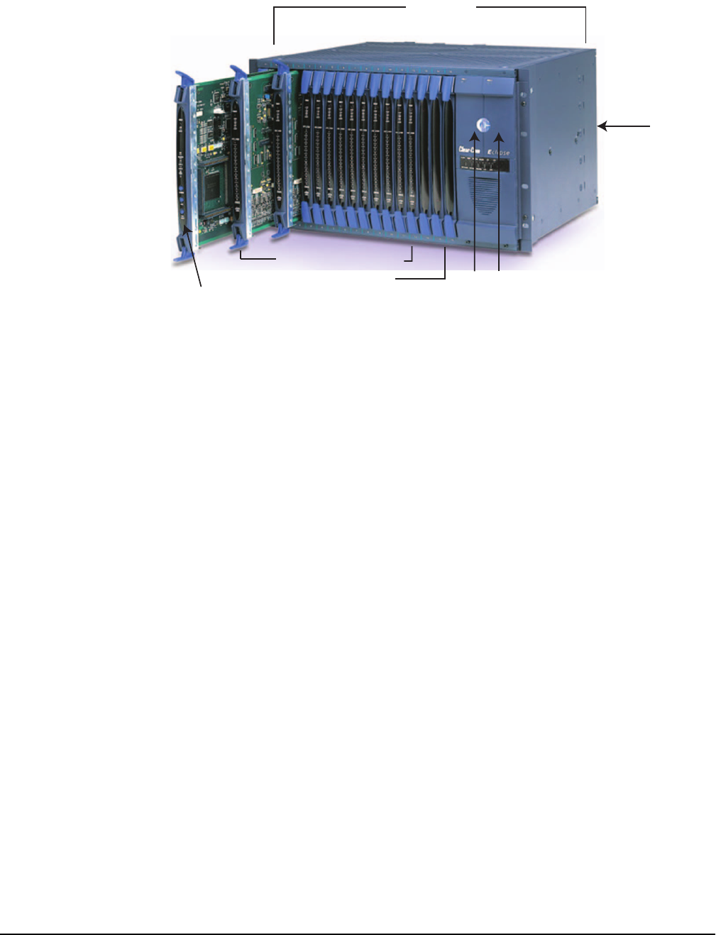
Figure 1-1: The Eclipse Omega Matrix Assembly
Note: The term “central matrix” is used to differentiate the
system’s core hardware and software from the connected
intercom panels and interfaces. The central matrix itself
consists of the matrix hardware and the ECS application.
MATRIX CHASSIS
The matrix chassis is a metal rectangular box which measures six rack
units high and 19-inches wide (26.9 cm x 48.3 cm). It has slots for 17
circuit cards and 2 power supplies.
RJ-45 and fiber-optic connectors are located on removable plates on
the rear of the chassis. These connect the circuit cards to intercom
devices and media such as panels, interfaces, 4-wire audio
equipment, wireless equipment and fiber-optic cables.
CIRCUIT CARDS
The matrix holds two types of circuit cards: system cards and port
cards. The cards slide vertically into the front of the matrix and connect
to the matrix’s backplane.
CPU Card
The CPU card is the master configuration card in the Eclipse Omega
system. It provides the serial data and Ethernet connection to the
connected PC computer. The CPU card also coordinates the data flow
between the other cards in the system, allowing them to communicate
with each other. The computer memory chip which stores four
complete system configurations is located on the CPU card, so that a
Eclipse Frame
Twelve 16-Port Circuit Cards
Dual Redundant
Power Supplies
RJ-45 Connectors
("Ports") on Back Panel
CPU Card
Three Spare Expansion Card Slots