
Instruction Manual
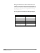

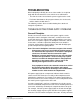
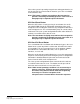
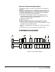
Table Of Contents
- The Eclipse Omega Matrix System: An Overview
- Operation
- The Eclipse Omega Matrix and Circuit Cards
- Front-Panel Controls and Lights
- Central Processor Unit (CPU) Card Description
- Analog Port Card Description
- Power Supply Description
- Connecting the Matrix
- Eclipse Fiber Linking
- Eclipse E-QUE Interface
- Eclipse IVC-32 Interface
- Eclipse LMC-64 Interface
- Installation
- Reconnecting the CPU Card’s Backup Battery
- Verifying the Shipment
- Unpacking the System
- Installing the Eclipse Omega Matrix
- Installing Power Supplies
- Installing the Rear RJ-45 Connector Panels
- Installing Rear RJ-45 Connector Panels in the Field
- Installing CPU Cards
- Installing Analog Port and Expansion Cards
- Wiring Audio Devices to the Matrix
- Wiring CPU Card Interfaces
- GPI/RLY Interface Connector
- RS-232 DB-9 Connector
- Alarm I/O Connector
- General-Purpose Outputs Connector (GP OUT)
- General-Purpose Inputs Connector (GP IN)
- Local Area Network Connectors (LAN1 and LAN2)
- E1/T1 Matrix to Matrix Crossover Cable
- E1/T1 Straight Cable Connections
- E1 to FreeSpeak/CellCom Antenna Pinout
- Maintenance
- Specifications
- Glossary
- Limited Warranty
- Technical Support & Repair Policy
Clear-Com
Eclipse Omega Instruction Manual
8-8
Specific Troubleshooting Examples
The following examples describe specific problems and suggested
solutions.
Problem: A port light on an analog port interface does not
illuminate, although there is a panel attached to that port
1. Check the panel and the wiring leading to it.
2. Check the Frame Data light. If there is no indication of matrix
communication to this interface while the other interfaces in the
matrix are communicating, reset the interface.
3. Replace the interface cards.
4. Replace the panel.
Problem: Audio sounds low or distorted from a panel
1. Check the matrix’s currently active CPU card’s power lights. If any of
the lights are not lit, replace the card.
2. Check the analog port input and output gain settings for the port in
ECS.
3. Check the panel’s listen-level adjustment settings in ECS.
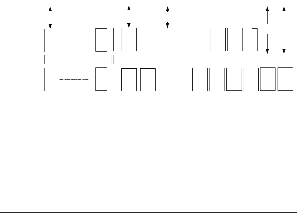
SYSTEM BLOCK DIAGRAM
Figure 8-1: System Block Diagram
INTERFACE CARD
INTERFACE REAR CARD
INTERFACE CARD
INTERFACE REAR CARD
MAIN BACKPLANE INTERFACE MODULE BACKPLANE
PSU PSU
ALARM
CARD
CONFIG
CARD
CONFIG
CARD
MVX16A
CARD
TERMINATOR CARD
POWER
SUPPLY
CONN
POWER
SUPPLY
CONN
MVX16A
REAR
CARD
ANALOG
STATION
INTERFACES
CONFIG
REAR
CARD
LAN1, LAN2,
GPI, GPO, GPI/RLY,
RS232 SERIAL &
ALARM INTERFACES
TERMINATOR CARD
INTERFACE TO
GPI/RLY &
2/4 WIRE
INTERFACES
Fibre-Net
front card
(optional)
Fibre-Net
rear card
(optional)
MVX16A
CARD
MVX16A
REAR
CARD
E-Que
front card
(optional)
E-Que
rear card
(optional)