
Instruction Manual

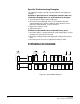
Table Of Contents
- The Eclipse Omega Matrix System: An Overview
- Operation
- The Eclipse Omega Matrix and Circuit Cards
- Front-Panel Controls and Lights
- Central Processor Unit (CPU) Card Description
- Analog Port Card Description
- Power Supply Description
- Connecting the Matrix
- Eclipse Fiber Linking
- Eclipse E-QUE Interface
- Eclipse IVC-32 Interface
- Eclipse LMC-64 Interface
- Installation
- Reconnecting the CPU Card’s Backup Battery
- Verifying the Shipment
- Unpacking the System
- Installing the Eclipse Omega Matrix
- Installing Power Supplies
- Installing the Rear RJ-45 Connector Panels
- Installing Rear RJ-45 Connector Panels in the Field
- Installing CPU Cards
- Installing Analog Port and Expansion Cards
- Wiring Audio Devices to the Matrix
- Wiring CPU Card Interfaces
- GPI/RLY Interface Connector
- RS-232 DB-9 Connector
- Alarm I/O Connector
- General-Purpose Outputs Connector (GP OUT)
- General-Purpose Inputs Connector (GP IN)
- Local Area Network Connectors (LAN1 and LAN2)
- E1/T1 Matrix to Matrix Crossover Cable
- E1/T1 Straight Cable Connections
- E1 to FreeSpeak/CellCom Antenna Pinout
- Maintenance
- Specifications
- Glossary
- Limited Warranty
- Technical Support & Repair Policy

Clear-Com
Eclipse Omega Instruction Manual
8-5
Problem: The power supply lights do not illuminate on any
cards in the matrix
In this situation, the most probable problem is that the matrix’s power
supplies are not sending out any electric current, since none of the
cards are receiving power. Although less likely, the problem may be in
the matrix’s backplane connectors.
The following procedure may help to isolate where the trouble is
occurring:
Check the power supplies’ alarm lights. If the power alarm lights are
indicating a problem with the power supply, swap it out with a new
power supply.
• If this repairs the problem, the problem was in the power supply.
• If the problem persists even after the power supply has been
replaced, the problem is in the matrix’s backplane connectors.
Send the matrix back to Clear-Com for repair or replacement. In
the meantime another matrix can be substituted for the damaged
one. Clear-Com may ship a spare matrix to use while the
damaged matrix is being repaired depending on the support
status. Please refer to the warranty and support sections in this
manual.
Problem: The power supply lights do not illuminate on one
of the two CPU cards
When the system is functioning properly, the power-supply lights on
both CPU cards illuminate. If the power-supply lights on a CPU card
fail to illuminate, the problem may be with the card itself, or with the
backplane connectors that carry the electric current from the power
supplies to the cards. The backplane connectors are part of the
infrastructure of the matrix and are not serviceable by field personnel.
The following procedure may help to isolate where the trouble is
occurring:
1. Swap the CPU cards. Put the first card in the second CPU slot and
the second card in the first CPU slot. The problem will follow the
card or the slot.
• If the power supply lights do not illuminate on the bad card (the
card with the lights out) when it is inserted in the other CPU slot,
the problem is probably in the card.
• If the power-supply lights on the bad card illuminate when the card
is inserted in the other CPU slot, the problem is probably not in
the card itself. The problem may be with the backplane
connectors or power supplies.
2. Check the power supplies’ alarm lights. If the alarm lights are
indicating a problem with the power supply, swap it out with a new
power supply.
• If this repairs the problem, the problem was in the power supply.