
Instruction Manual
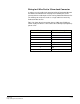

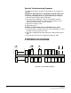
Table Of Contents
- The Eclipse Omega Matrix System: An Overview
- Operation
- The Eclipse Omega Matrix and Circuit Cards
- Front-Panel Controls and Lights
- Central Processor Unit (CPU) Card Description
- Analog Port Card Description
- Power Supply Description
- Connecting the Matrix
- Eclipse Fiber Linking
- Eclipse E-QUE Interface
- Eclipse IVC-32 Interface
- Eclipse LMC-64 Interface
- Installation
- Reconnecting the CPU Card’s Backup Battery
- Verifying the Shipment
- Unpacking the System
- Installing the Eclipse Omega Matrix
- Installing Power Supplies
- Installing the Rear RJ-45 Connector Panels
- Installing Rear RJ-45 Connector Panels in the Field
- Installing CPU Cards
- Installing Analog Port and Expansion Cards
- Wiring Audio Devices to the Matrix
- Wiring CPU Card Interfaces
- GPI/RLY Interface Connector
- RS-232 DB-9 Connector
- Alarm I/O Connector
- General-Purpose Outputs Connector (GP OUT)
- General-Purpose Inputs Connector (GP IN)
- Local Area Network Connectors (LAN1 and LAN2)
- E1/T1 Matrix to Matrix Crossover Cable
- E1/T1 Straight Cable Connections
- E1 to FreeSpeak/CellCom Antenna Pinout
- Maintenance
- Specifications
- Glossary
- Limited Warranty
- Technical Support & Repair Policy
Clear-Com
Eclipse Omega Instruction Manual
7-25
Wiring for 4-Wire Port to 3.5mm Jack Connector
In order to use the audio level metering facility of Production Maestro
Pro without an LMC-64 level metering card a 4-Wire port can be
connected to the audio input of a PC running Production Maestro Pro.
The 4-Wire port can then to used as a single audio level meter by
Production Maestro Pro.
Table 7-6 shows the pin connection from a 4-Wire port (RJ45) to a
3.5mm audio jack which is connected to the audio input (microphone)
port on a PC.
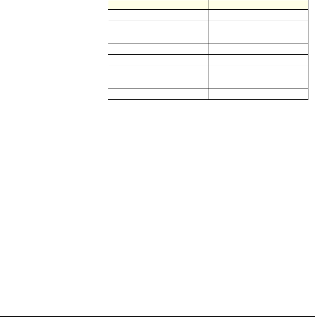
Table 7-6: Pin Connection for 4-Wire to PC Audio Cable
Matrix 4-Wire Port PC Audio 3.5 mm jack
1N/C
2N/C
3N/C
4Tip
5Ring
6N/C
7N/C
8N/C