
Instruction Manual

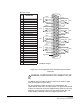
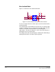
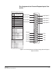
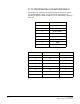
Table Of Contents
- The Eclipse Omega Matrix System: An Overview
- Operation
- The Eclipse Omega Matrix and Circuit Cards
- Front-Panel Controls and Lights
- Central Processor Unit (CPU) Card Description
- Analog Port Card Description
- Power Supply Description
- Connecting the Matrix
- Eclipse Fiber Linking
- Eclipse E-QUE Interface
- Eclipse IVC-32 Interface
- Eclipse LMC-64 Interface
- Installation
- Reconnecting the CPU Card’s Backup Battery
- Verifying the Shipment
- Unpacking the System
- Installing the Eclipse Omega Matrix
- Installing Power Supplies
- Installing the Rear RJ-45 Connector Panels
- Installing Rear RJ-45 Connector Panels in the Field
- Installing CPU Cards
- Installing Analog Port and Expansion Cards
- Wiring Audio Devices to the Matrix
- Wiring CPU Card Interfaces
- GPI/RLY Interface Connector
- RS-232 DB-9 Connector
- Alarm I/O Connector
- General-Purpose Outputs Connector (GP OUT)
- General-Purpose Inputs Connector (GP IN)
- Local Area Network Connectors (LAN1 and LAN2)
- E1/T1 Matrix to Matrix Crossover Cable
- E1/T1 Straight Cable Connections
- E1 to FreeSpeak/CellCom Antenna Pinout
- Maintenance
- Specifications
- Glossary
- Limited Warranty
- Technical Support & Repair Policy
Clear-Com
Eclipse Omega Instruction Manual
7-21
Pin Assignments for General-Purpose Inputs Con-
nector
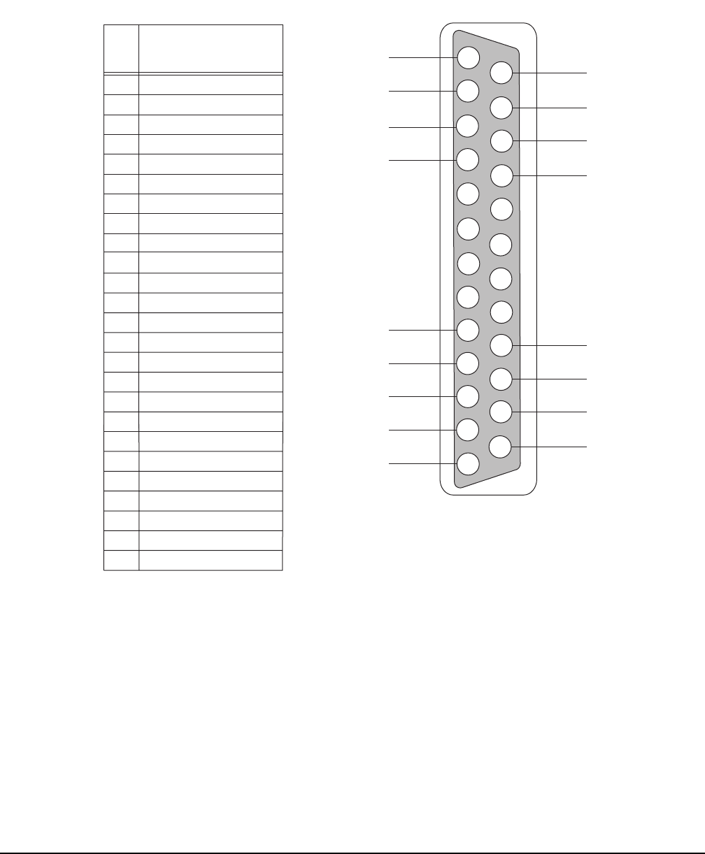
Figure 7-14: Pin Assignments for Eclipse Omega General-Purpose
Inputs Connector
1
2
3
4
5
6
7
8
9
10
11
12
13
14
15
16
17
18
19
20
21
22
23
24
25
PIN
DESCRIPTION
1
2
3
4
Logic Input 3
Logic Input 4
N/A
N/A
N/A
N/A
Ground
Ground
Ground
Ground
Logic Input 5
Logic Input 6
Logic Input 7
Logic Input 8
N/A
5
6
7
8
9
10
11
12
13
14
16
17
18
19
20
21
22
23
24
25
15
N/A
N/A
N/A
Voltage In+
Ground
Ground
Ground
Ground
Ground
V IN+
V IN+
V IN–
V IN–
Ground
DB-25 Female Connector
Logic Input 1
Logic Input 2
Voltage In+
Voltage In-
Voltage In-
Logic Input 1
Logic Input 2
Logic Input 3
Logic Input 4
Logic Input 5
Logic Input 6
Logic Input 7
Logic Input 8