
Instruction Manual
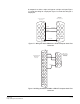

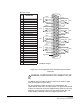
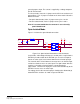
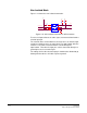
Table Of Contents
- The Eclipse Omega Matrix System: An Overview
- Operation
- The Eclipse Omega Matrix and Circuit Cards
- Front-Panel Controls and Lights
- Central Processor Unit (CPU) Card Description
- Analog Port Card Description
- Power Supply Description
- Connecting the Matrix
- Eclipse Fiber Linking
- Eclipse E-QUE Interface
- Eclipse IVC-32 Interface
- Eclipse LMC-64 Interface
- Installation
- Reconnecting the CPU Card’s Backup Battery
- Verifying the Shipment
- Unpacking the System
- Installing the Eclipse Omega Matrix
- Installing Power Supplies
- Installing the Rear RJ-45 Connector Panels
- Installing Rear RJ-45 Connector Panels in the Field
- Installing CPU Cards
- Installing Analog Port and Expansion Cards
- Wiring Audio Devices to the Matrix
- Wiring CPU Card Interfaces
- GPI/RLY Interface Connector
- RS-232 DB-9 Connector
- Alarm I/O Connector
- General-Purpose Outputs Connector (GP OUT)
- General-Purpose Inputs Connector (GP IN)
- Local Area Network Connectors (LAN1 and LAN2)
- E1/T1 Matrix to Matrix Crossover Cable
- E1/T1 Straight Cable Connections
- E1 to FreeSpeak/CellCom Antenna Pinout
- Maintenance
- Specifications
- Glossary
- Limited Warranty
- Technical Support & Repair Policy
Clear-Com
Eclipse Omega Instruction Manual
7-19
general-purpose input. The current is supplied by a voltage output on
the GP IN connector.
To select a mode, move the J1 jumper on the CPU rear card to one of
two positions. The J1 jumper is located on the inner-matrix side of the
DB-25 connector.
• For opto-isolated mode, fit the J1 jumper across pins 1 and 2.
• For non-isolated mode, fit the J1 jumper across pins 2 and 3.
Note: It is recommended that the connector is set to the fully
opto-isolated mode.
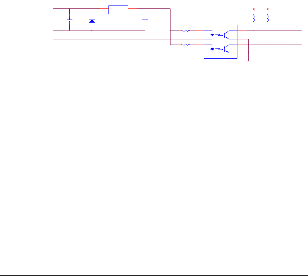
Opto-Isolated Mode
Figure 7-12 shows the opto-isolated connection.
Figure 7-12: Opto-Isolated Connection to GPI Connector
In this mode, a DC voltage of between 7 and 24 volts is required at the
EXTVIN+ pin with relation to the EXTVIN– pin. To cause an input to
detect an active signal, current must flow from the relevant input pin.
The external device should draw no current to cause an inactive input
and at least 5 mA to cause an active input. The opto-isolator drive line
contains a 1.5 kOhm resistor to limit the current through the
opto-isolator. Therefore the input pins can be connected directly to the
EXTVIN– level to cause an active input.
The voltage level at the external input pin should not be allowed to go
below EXTVIN– or above +6 V with respect to EXTVIN–.
+
C
10uF_10V
D
BYG22D
+
C
10uF_25V
INPUT 1EXTVIN-
EXTERNAL INPUT 2
EXTVIN+
INPUT 2
R29 1.5K
U
LM78L05ACM
VIN
8
VOUT
1
7-24V
R30 1.5K
U
MOCD207-M
1
3
2
4
8
7
6
5
EXTERNAL INPUT 1
R
33K2
+3V3
R
33K2
+3V3