
Instruction Manual
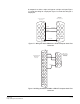

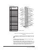
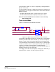
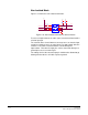
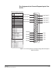
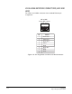
Table Of Contents
- The Eclipse Omega Matrix System: An Overview
- Operation
- The Eclipse Omega Matrix and Circuit Cards
- Front-Panel Controls and Lights
- Central Processor Unit (CPU) Card Description
- Analog Port Card Description
- Power Supply Description
- Connecting the Matrix
- Eclipse Fiber Linking
- Eclipse E-QUE Interface
- Eclipse IVC-32 Interface
- Eclipse LMC-64 Interface
- Installation
- Reconnecting the CPU Card’s Backup Battery
- Verifying the Shipment
- Unpacking the System
- Installing the Eclipse Omega Matrix
- Installing Power Supplies
- Installing the Rear RJ-45 Connector Panels
- Installing Rear RJ-45 Connector Panels in the Field
- Installing CPU Cards
- Installing Analog Port and Expansion Cards
- Wiring Audio Devices to the Matrix
- Wiring CPU Card Interfaces
- GPI/RLY Interface Connector
- RS-232 DB-9 Connector
- Alarm I/O Connector
- General-Purpose Outputs Connector (GP OUT)
- General-Purpose Inputs Connector (GP IN)
- Local Area Network Connectors (LAN1 and LAN2)
- E1/T1 Matrix to Matrix Crossover Cable
- E1/T1 Straight Cable Connections
- E1 to FreeSpeak/CellCom Antenna Pinout
- Maintenance
- Specifications
- Glossary
- Limited Warranty
- Technical Support & Repair Policy
Clear-Com
Eclipse Omega Instruction Manual
7-17
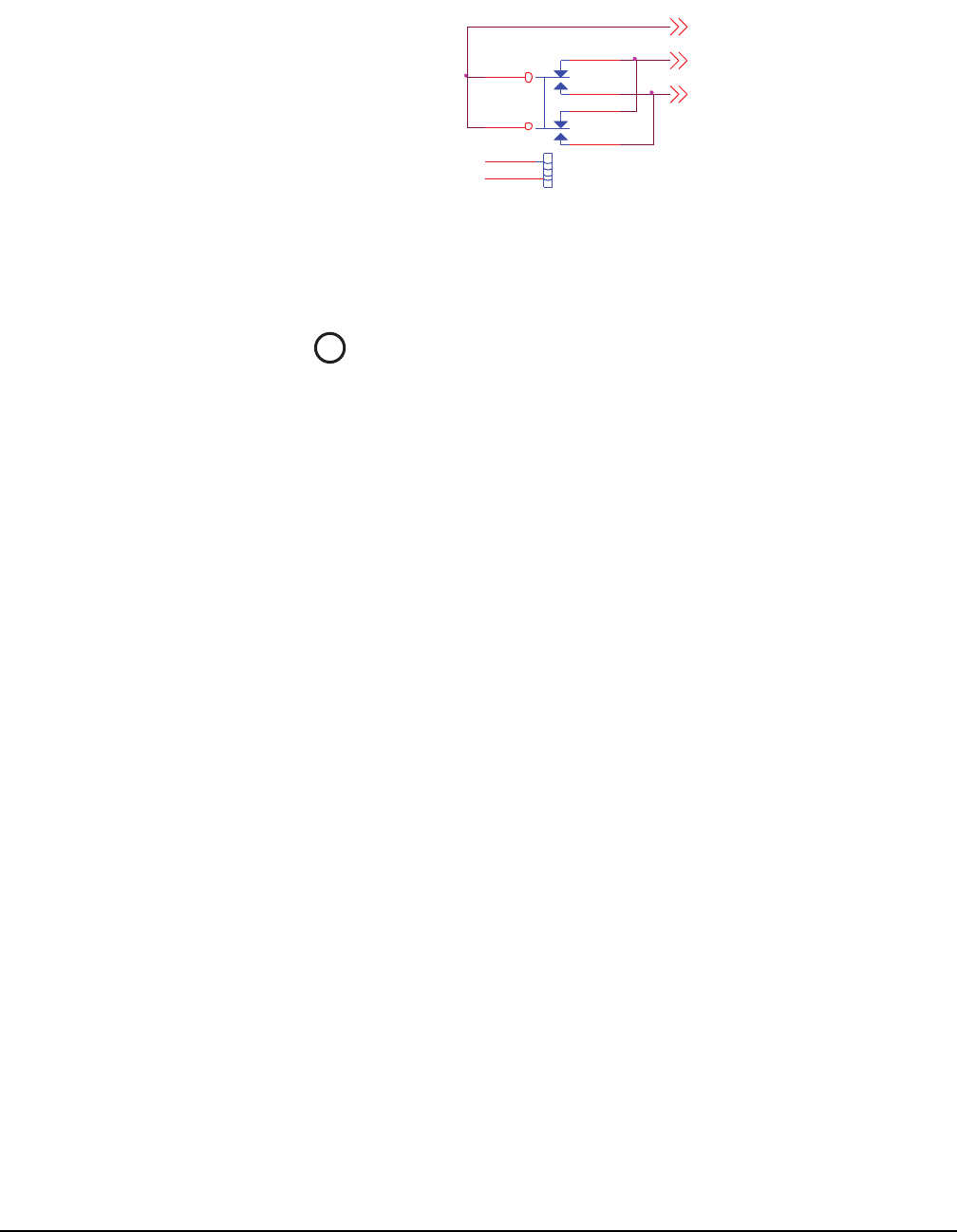
Figure 7-10: Eclipse Omega Matrix’s Double-Pole Double-Throw
Alarm Relay
GENERAL-PURPOSE OUTPUTS CONNECTOR
(GP OUT)
The DB-25 connector labeled “GP OUT” connects the matrix to eight
double-pole double-throw (DPDT) relays with contact ratings of 30
VDC at 1A.
Each general-purpose output has a relay inside the Eclipse Omega
matrix. When a general-purpose output is inactive, the associated
“common” pin on the GP OUT connector will be shorted to the relevant
“normally closed” pin. When a general-purpose output becomes active,
the short between the “common” pin is broken and a new connection is
made between the “common” pin and the “normally open” pin.
ALARM_COM
RL1
RELAY DPDT
3
2
4
8
9
7
1
10
ALARM_NC
ALARM_NO
4