CLEAR-COM ECLIPSE ICS-22 SPEAKER PANEL INSTRUCTION MANUAL
ICS-22 Speaker Panel Instruction Manual © 2000, 2008 Vitec Group Communications Ltd. All Rights Reserved. Part Number 810264Z Rev. 2 Vitec Group Communications LLC 850 Marina Village Parkway Alameda, CA 94501 U.S.A Vitec Group Communications Ltd 7400 Beach Drive IQ Cambridge Cambridgeshire United Kingdom CB25 9TP Vitec Group Communications Room 1806, Hua Bin Building No. 8 Yong An Dong Li Jian Guo Men Wai Ave Chao Yang District Beijing, P.R.
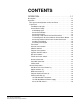
CONTENTS OPERATION . . . . . . . . . . . . . . . . . . . . . . . . . . . . . . 1-1 Description . . . . . . . . . . . . . . . . . . . . . . . . . . . . . . . . . . . . . . . . . . . . 1-1 Operation . . . . . . . . . . . . . . . . . . . . . . . . . . . . . . . . . . . . . . . . . . . . . 1-2 ECS System Configuration for ICS-22 Panels . . . . . . . . . . . . . . . 1-2 Front Panel . . . . . . . . . . . . . . . . . . . . . . . . . . . . . . . . . . . . . . . . . . 1-3 Talk Button and Light. . . . . . . . . . . .
QUICK START . . . . . . . . . . . . . . . . . . . . . . . . . . . . . 2-1 INSTALLATION . . . . . . . . . . . . . . . . . . . . . . . . . . . . 3-1 MAINTENANCE. . . . . . . . . . . . . . . . . . . . . . . . . . . . 4-1 Troubleshooting tips . . . . . . . . . . . . . . . . . . . . . . . . . . . . . . . . . . . . . 4-1 Technical Reference . . . . . . . . . . . . . . . . . . . . . . . . . . . . . . . . . . . . . 4-3 Bills of Materials . . . . . . . . . . . . . . . . . . . . . . . . . . . . . . . . . . . . . .
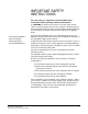
IMPORTANT SAFETY INSTRUCTIONS For your safety, it is important to read and follow these instructions before operating a ICS-22 speaker panel: (1) WARNING: To reduce the risk of fire or electric shock, do not expose a ICS-22 speaker panel to rain or moisture. Do not operate a ICS-22 speaker panel near water, or place objects containing liquid on it. Do not expose a ICS-22 speaker panel to splashing or dripping water. Please read and follow these instructions before operating a ICS-22 speaker panel.
CAUTION RISK OF ELECTRIC SHOCK DO NOT OPEN This symbol alerts you to the presence of uninsulated dangerous voltage within the product's enclosure that might be of sufficient magnitude to constitute a risk of electric shock. Do not open the product's case. This symbol informs you that important operating and maintenance instructions are included in the literature accompanying this product.
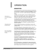
1 OPERATION DESCRIPTION The Clear-Com ICS-22 is a two-channel speaker panel designed for use in theatres, live performances, industrial environments, and small television facilities. It features excellent speech intelligibility, even in high noise levels, and can be customized through its programmable options. • The ICS-22 is a two-channel speaker panel. • The panel must be powered locally.
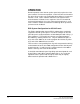
OPERATION Normal operation of the ICS-22 speaker panel only requires the front panel controls. For intercom operation, set the intercom level control to the desired level and press the talk button when talking. If a headset or handset is used, set the sidetone control for each channel for the desired amount of sidetone in the earphone.
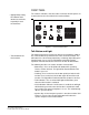
FRONT PANEL • Appropriately setting the sidetone level decreases confusion, especially in loud environments. The controls, indicators, and connectors on the ICS-22 front panels are shown below and are described in the text that follows. A VOX Call Waiting B Talk/Listen Select Panel Mic Answer Back Intercom Level Headset Program Level Off Sidetone Talk On Speaker Figure 1-1: ICS-22 Front Panel Talk Button and Light • The talk button has five functions.
• Note: The call-waiting light does not light when a call is received from a programmed label. Answer-Back Facility The answer-back facility answers calls from panels or interfaces that the panel has not currently selected. Call-Waiting Light This dual-function light: • is steadily lit when a call signal is received • flashes to indicate a call waiting signal, which has priority over a call signal.
Answering Another Call from the Answer-Back Stack To answer another call from the answer-back stack: • Note: The configuration program can be set to also send an audible signal through the speaker, which can only be heard if the intercom level is turned up. • If the calling panel disconnected the call, the call waiting light will flash. • If the receiving panel disconnected the call, a call from another unselected label will be activated when the answer-back button is released.
Program-Level Control This control sets the program input audio level heard in the headset or panel speaker. Speaker ON/OFF Switch This switch turns the front-panel speaker on or off. It also controls whether the tone alert is heard through the speaker. The speaker volume will automatically dip when the talk function is set, unless the VOX function is enabled. Mic-Select Switch • The VOX feature provides operators with a voice activated option.
Panel-Mic Connector • To install a GM-9 or GM-18 microphone there are four steps. Clear-Com recommends that the GM-9 (9-in. long) and GM-18 (18-in. long) plug-in panel microphones be used with the ICS-22. Both are the electret type. The 1/4-in. phone jack on the microphone mates with the panel-mic receptacle on the ICS-22’s front panel. To install a GM-9 or GM-18 microphone: 1. Remove the plastic plug from the jack, if present. 2.
POWER CONNECTION 4 5 PROGRAM INPUT • There are five internal connections. 3 MATRIX CONNECTOR VIEW FROM TOP OF ICS-22 321 • Option switches should not be changed from their factory settings. • Note: The ON position of each option switch is toward the circuit board and the OFF position is toward the front panel. The default position of the switches is the OFF position.
The pinout of this connector is as follows: • The Program Input can be set between -20 dBu to +10 dBu. Pin Number Function 1 Ground (Shield) 2 Positive Signal 3 Negative Signal Table 1-3: ICS-22 XLR Pinout Information PIN 1 2 3 1 ICS-22 PROGRAM INPUT CONNECTOR XLR CONNECTOR Figure 1-3: ICS-22 Program-Input Cable Wiring • The panel can obtain power from three different sources.
1-10 Vitec Group Communications ICS-22 Speaker Panel Instruction Manual
2 • Users can use the “Quick Start” approach to get their panels up and running in minutes. QUICK START 1. Unpack the unit and inspect it for any damage that may have occurred during shipping. 2. Set the option switches to the default (up) position. 3. Connect the RJ-45 connector to the Matrix frame. 4. Connect 14- to18-VAC power to the two-terminal, plug-on connector. 5. Install the ICS-22 into the USA standard four-gang outlet box. 6. Set listen levels and sidetones (see Figure 1-2 on page 1-8). 7.
2-2 Vitec Group Communications ICS-22 Speaker Panel Instruction Manual
3 • The ICS-22 runs on 14- to 18-VAC power. • Note: If the panel is installed in a DT-Box, the back cover of the DT-Box must first be removed. It is retained with four screws. Feed the power cable through one slot and fasten it to the strain relief as shown in Figure 1-2. INSTALLATION 1. Connect the 14- to 18-VAC power to the two-position terminal strip. Plug the terminal strip onto the P2 as shown in Figure 1-2 on page 1-6. 2.
3-2 Vitec Group Communications ICS-22 Speaker Panel Instruction Manual
4 MAINTENANCE TROUBLESHOOTING TIPS Listed below are some of the more common problems the panel may experience, their possible causes, and suggested solutions. Symptom System does not operate and the talk light does not turn on when talk button is pressed. • Sometimes when the talk light doesn’t work it’s because the panel isn’t receiving power. • When the system doesn’t operate, make sure there isn’t an incompatibility problem.
Symptom System feedback (acoustical). Solution 1. The intercom-level 1. Adjust. control at this panel or another panel is set too high. 2. The sidetone control 2. Adjust (see Figure at the panel or another 1-1 on page 1-2). panel is incorrectly adjusted. • System feedback can have three different causes. VOX problems. • VOX problems can be caused by incorrect sensitivity settings. • Note: VOX is intended for close-in operation. Cause The program signal sounds distorted. Rapid clicking noise. 3.
Vitec Group Communications ICS-22 Speaker Panel Instruction Manual Talk Mic Select Matrix Interface 16 VAC Talk/Listen Select Switch Panel Mic Headset Mic Rectifier B A VOX Power Microprocessor RMK Red / Green Talk/ VOX Microprocessor Mic Dip / Mute EQ/ LIM Sidetone Null Call Send & Receive Answer Back Speaker Dip Call Waiting Light Program Level Intercom Volume Program Mute Speaker On/Off Matrix Connector Balanced Program Input Headset Output Speaker TECHNICAL REFERENCE Fig
BLANK PAGE 4-4 Vitec Group Communications ICS-22 Speaker Panel Instruction Manual
C28 R16 Q1 R13 R17 C7 C14 C47 Q3 R18 R22 C31 R26 R36 C35 R39 CALL ALERT TONE LEVEL C32 IC9 R10 R9 C34 C18 C10 C11 R24 R11 P9 IC2 S3 R44 IC11 D14 C24 R28 C42 R53 1 IC10 D15 C19 R30 R6 C26 D5 1 S5 R27 C25 R46 C43 R15 R8 D8 J3 S4 C17 R54 C27 C39 R43 D11 Q5 IC8 P6 R1 IC5 R41 J1 R48 S2 R50 D7 C12 C21 Q4 D13 R29 R40 S1 C33 C36 COPYRIGHT (C) 1999 R33 R42 C8 D12 R7 D9 D10 D2 D16 P1 P2 P3 R4 Q2 D3 C5 R3 D6 ASSY #710470 C4 D4 R12 J2 W1 C41 R35
BILLS OF MATERIALS ICS-22 Main PCB (Part No. 710470) CAPACITORS Designator Description C8 C47 C1 C28 C6 C11 C24 C17 C41 C14 C5 C19 C27 C30 C26 C7 C46 C16 220 uF Aluminum 35V .01 uF Ceramic Disc 1.4KV 20% 22 uF Tantalum 16V 4.7 uF Tantalum 35V 4.7 uF Aluminum NP 50V .047 uF Mylar 100V 5% 100 uF Aluminum 35V 22 pF Ceramic SMD 50V 5% 47 pF Ceramic SMD 50V 5% 220 pF Ceramic SMD 50V 5% 470 pF Ceramic SMD 50V 5% .0022 uF Ceramic SMD 50V 10% C9 C20 C22 .0047 uF Ceramic SMD 50V 10% C13 C37 C38 C40 C31 C29 .
Designator R47 R51 R20 R22 R14 R33 R43 R18 R21 R42 R48 R28 R17 R52 R19 R38 R16 R24 R30 R31 R34 R39 R37 R41 R6 R12 R49 R50 R32 R26 R54 R8 R9 R10 R11 R2 R3 R1 R7 R4 R36 R40 R23 R29 Description 301 OHM 1/10 SMD 1% 432 OHM 1/10 SMD 1% 825 OHM 1/10 SMD 1% 1.00K OHM 1/10 SMD 1% 1.50K OHM 1/10 SMD 1% 2.00K OHM 1/10 SMD 1% 2.74K OHM 1/10 SMD 1% 6.19K OHM 1/10 SMD 1% 6.81K OHM 1/10 SMD 1% 8.25K OHM 1/10 SMD 1% 12.1K OHM 1/10 SMD 1% 15.0K OHM 1/10 SMD 1% 20.0K OHM 1/10 SMD 1% 56.
DESIGNATOR Q2 D1 D2 D3 D4 D5 D6 D11 D13 Q5 IC9 Q1 Q3 D7 D10 Q4 C10 DESCRIPTION Transistor 2907A PNP 60V 600MA Diode BAV99 DUAL DIODE Transistor MPSA14 DNPN 30V 300MA IC DG444 QUAD CMOS ANALOG SW Transistor J175 P-CHANNEL JFET Diode 5.1V 5% ZENER 1/4W Transistor MPSA64 DPNP 30V 500MA IC MICROPROCESSOR, KB/MR SERIES QTY 1 8 1 1 2 2 1 1 MISCELLANEOUS Designator P4 P10 R29 S5 S4 D14 S4 S5 S2 S3 S1 4-8 Description Connector 5 POS, SCREW TERM XLR 4 PIN M FLSH MNT Connector 3 POS, SCREW TERM.
XLR 4 XLR 3 P7 1 2 P5 W4 JUMPER W3 JUMPER A D5 BAV99 2 1 D6 BAV99 3 1 2 3 C46 470pF JP1 1 2 4 + R35 100* C6 4.7uF 2 3 1 3 R4C 470K* IC9A 6 2 1 2 1 2 1 7 4 13 2 DG444 R4B 470K* C7 470pF B 2 R17 6.8K* +V3 C32 .1uF 8 R19 12.1K* + +V1 VDD C4 1uF Q2 MMBT2907A 1 R3A 47K* 1 1 1 +V1 R52 8.2K* R51 300* VOX R3B 47K* 1 2 C10 .1uF IC2A LM833 Bias-1 4 5 C11 4.7uF R21 2K* C R20 430* 3 C18 .
BLANK PAGE 4-10 Vitec Group Communications ICS-22 Speaker Panel Instruction Manual
Figure 4-4: VOX PCB Component Layout (part no. 710472) ICS-22 VOX PCB (Part No. 710472) CAPACITORS Designator C13 C10 C8 C12 C1 C2 C3 C5 C4 C6 C9 C11 Vitec Group Communications ICS-22 Speaker Panel Instruction Manual Description 1 uF Aluminum NP 50V 10% 470 pF Ceramic Disc 50V 10% 4.7 uF Tantalum 16V .1 uF Monolithic 50V 10% 680 pF Ceramic Disc 50V 10% .022 uF Monolithic 50V 10% .
Designator C14 Description 22 uF Tantalum 10V 10% Qty 1 RESISTORS Designator R1 R12 R16 R17 R13 R2 R6 R4 R8 R11 R15 R14 R3 R10 R9 R5 Description 4.7K OHM 1/4 Carbon Film 5% 6.8K OHM 1/4 Carbon Film 5% 1.
Vitec Group Communications ICS-22 Speaker Panel Instruction Manual 2 10 7 D9 1N4740A 10V +V4 +V1 9 A C11 220uF R10D 10K X 5I +V1 Bias 5 R10E 10K X 5I R10C 10K X 5I R3E 10K X 5I + 6 Bias-2 4 9 1 IC1A LF353 3. ALL DIODES ARE 1N4148 B 2. ALL CAPACITORS ARE LISTED IN MICROFARADS + R3D 10K X 5I 1N4148 D3 R11 100K* C5 680pF 1. ALL RESISTORS ARE 1/10W 5% LISTED IN OHMS NOTES: (UNLESS OTHERWISE SPECIFIED) C14 22uF TANT + - C1 .1uF D1 1N5231B 5.
BLANK PAGE 4-14 Vitec Group Communications ICS-22 Speaker Panel Instruction Manual
P3 R7 T2 R2 Z3 C6 R5 IC3 R8 C5 R6 C3 C2 T1 R1 C1 R10 C4 P2 Q1 R4 16-18 VAC R3 PWR R9 D1 IC2 D3 P4 IC1 ASSY #710533 J1 P1 CLEAR-COM COPYRIGHT (C) 1999 Figure 4-6: Matrix Option PCB Component Layout (part no. 710533) Matrix Option PCB (Part No. 710533) CAPACITORS Designator C6 C5 C4 C3 C2 C1 Vitec Group Communications ICS-22 Speaker Panel Instruction Manual Description 10 uF Aluminum 50V .022 uF Monolithic 50V 10% .1 uF Monolithic 100V 10% .
RESISTORS Designator R5 R6 R8 R9 R1 R7 R10 R2 R4 R3 Description 2K OHM 1/4 Carbon Film 5% 47K OHM 1/4 Carbon Film 5% 1.5K OHM 1/4 Carbon Film 5% 330 OHM 1/4 Carbon Film 5% 100 OHM 1/4 Carbon Film 5% 2.2M OHM 1/4 Carbon Film 5% 10K OHM X5 SIP ISOLATED 4.7K OHM X 4 SIP ISOLATED 100K OHM X4 SIP ISOLATED Qty 1 1 1 1 2 1 1 1 1 DIODES AND TRANSISTORS Designator D3 Description Diode 1N4148 SIGNAL 10MA 75PIV Transistor TIP41 NPN 40V 6A Diode 1.
A PROGRAMMING / TEST / INTERROGATION R4A 4.7K B Q1 TIP41 P4 7 R3D 100K 1 10K IC3A LM833 R2C 5 VDD + 13 12 11 4 3 2 Programming / Test / Vdd / Interrogation Connection R4D 4.7K VDD 3 2 3 VDD 8 RB0 RB1 RB2 RB3 RB4 RB5 6 C RC0 RC1 RC2 RC3 RC4 RC5 10 9 8 7 6 5 IC2 PIC16C505P /Ch. A P1 R2D 10K Latch Disable 7 8 P3 R5 2K D3 1N4148 R2E 10K VDD R10 2.2M D C4 .1uF 3 2 C3 .0022uF C5 .022uF 1.
BLANK PAGE 4-18 Vitec Group Communications ICS-22 Speaker Panel Instruction Manual
5 SPECIFICATIONS Note: 0 dBu is referenced to 0.775 V RMS Headset Microphone Pre-Amp Input Type Impedance Input Level Dynamic 1k ohm -55 dBu nominal; -10 dBu max.
AC Power Two-position, plug-on screw terminals Front Panel Connectors Panel Mic Headset: (1) 1/4-in. panel mounting jack (1) XLR-4M Front Panel Controls & Indicators Panel/headset-mic switch Program-level control Intercom-volume control Sidetone control Talk button Answer-back button VOX control Talk/listen selector Speaker on-off switch Talk light Call-waiting light (1) (1) (1) (1) (1) (1) (1) (1) (1) (1) (1) Environmental 32° to 122° F (0° to 50° C) Dimensions 8.25 in. W x 4.5 in. H x 1.75 in.
LIMITED WARRANTY Vitec Group Communications (VGC) warrants that at the time of purchase, the equipment supplied complies with any specification in the order confirmation when used under normal conditions, and is free from defects in workmanship and materials during the warranty period.
Telephone for Europe, Middle East and Africa: +49 40 6688 4040 or +44 1223 815000 Telephone for the Americas and Asia: +1 510 337 6600 Email: vitec.support@AVC.de Once the standard warranty period has expired, the User Support Center will continue to provide telephone support if you have purchased an Extended Warranty. For latest contact information please refer to the Service and Support section at www.clearcom.com.
purchase of an extended warranty extends to five years the warranty of any product offered with a standard two-year warranty. The total warranty period will not extend beyond five years. Note: VGC does not offer warranty extensions on UHF wireless intercom systems, or on any product with a 1-year or 90-day warranty. LIABILITY THE FOREGOING WARRANTY IS VGC'S SOLE AND EXCLUSIVE WARRANTY.
iv Vitec Group Communications Warranty