
Instruction manual

Clear-Com Communication Systems
Eclipse-32 Matrix Instruction Manual
3-14
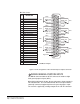
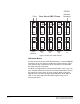
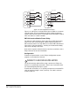
IMF-3 Interface Module Frame Wiring
To Matrix
To connect the GPI-6 to the matrix, plug one end of an RJ-45 cable
(eight wires with no reversal) into the GPI/RLY INTERFACE connector
on the back of the matrix. Plug the other end into the top RJ-45 (CH. A
MATRIX) connector for the GPI-6.
To connect an additional GPI-6 interface, plug one end of a short
RJ-45 cable into the lower RJ-45 (CH. B MATRIX) for the first GPI-6.
Then, plug the other end into the top RJ-45 (CH. A MATRIX) connector
for the additional GPI-6. Additional GPI-6 interfaces are added in the
same way, using daisy-chain wiring. If multiple GPI-6 interfaces are
required the inputs in the first will be numbered 1 through 6, the inputs
in the second will be numbered 7 through 12, etc. RLY-6 interfaces can
be mixed in this daisy-chained scheme. The maximum combined
length of all the RJ-45 cables should not exceed 20 ft. (6 m).
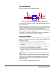
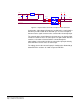
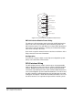
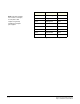
To External Device
To connect external devices to the GPI-6 interface, use the two DB-9M
connectors on the rear cable assembly panel for the interface. Figure
3-11 shows the pin assignment of these connectors as viewed from the
matrix side of the connector.
If a DB-9F is plugged into the connector labeled CH. A I/O, inputs 1
through 3 are available on that connector. The connector labeled CH.
B I/O has inputs 4 through 6. In Figure 3-11, the labels on the pins
apply to either connector.
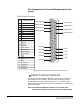
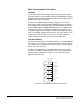
Figure 3-11: GPI-6 Interface DB-9M Connector Pinout
1
2
9
8
7
6
5
4
3
#2/5 Input A
#3/6 Input A
Ground
#1/4 Input A
#1/4 Input B
#2/5 Input B
Ground
Power Sourc
e
GPI-6 I/O DB 9M
#3/6 Input B