
Instruction manual

Clear-Com Communication Systems
Eclipse-32 Matrix Instruction Manual
3-11
The following sections give an overview of the wiring of these
interfaces. For more detailed discussion of wiring of interfaces in
general, see the manual Eclipse Matrix Installation Manual (part
810298Z).
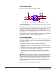
RLY-6 Interface Wiring
The RLY-6 relay interface module connects up to six programmable
relays to the matrix so that each relay is directly controlled from the
matrix. Multiple RLY-6 interfaces can be daisy chained to provide
connection of up to 60 relays to the matrix.
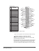
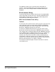
IMF-3 Interface Module Frame Wiring
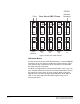
To Matrix
To connect the RLY-6 interface to the matrix, plug one end of an RJ-45
cable (eight wires with no reversal) into the GPI/RLY INTERFACE
connector on the back of the matrix. Plug the other end into the top
RJ-45 (CH. A MATRIX) connector for the RLY-6.
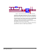
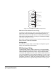
To connect an additional RLY-6 interface, plug one end of a short
RJ-45 cable into the lower RJ-45 (CH. B MATRIX) for the first RLY-6.
Then, plug the other end into the top RJ-45 (CH. A MATRIX) connector
for the additional RLY-6. Additional RLY-6 interfaces are added in the
same way, using daisy-chain wiring. If there are multiple RLY-6
interfaces, the relays in the first will be numbered 1 through 6, the
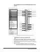
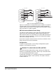
second will be numbered 7 through 12, etc. If both GPI-6 and RLY-6
interfaces are used in the frame the GPI-6 interfaces must be placed
before the RLY-6 interfaces (see Figure 3-9 below).
The maximum combined length of all the RJ-45 cables should not
exceed 20 ft. (6 m).