
Instruction manual

Clear-Com Communication Systems
Eclipse-32 Matrix Instruction Manual
3-10
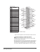
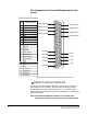
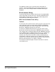
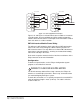
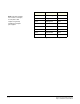
Pin Assignments for General-Purpose Inputs Con-
nector
Figure 3-8: Pin Assignments for Eclipse-32 GPI Connector
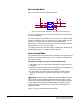
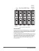
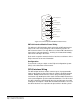
WIRING TO A GPI/RLY INTERFACE
The RJ-45 connector labeled “GPI/RLY” connects up to 10 RLY-6 or
GPI-6 interfaces to the matrix. RLY-6 and GPI-6 interfaces can be
mixed together up to the total limit of 60 items. Five RLY-6 and five
GPI-6 interfaces would provide 30 relays and 30 inputs for a total of 60
inputs and outputs.
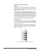
Note: If both GPI-6 and RLY-6 interfaces are used the GPI-6
interfaces are required to be placed first in the daisy chain.
1
2
3
4
5
6
7
8
9
10
11
12
13
14
15
16
17
18
19
20
21
22
23
24
25
PIN
DESCRIPTION
1
2
3
4
Logic Input 3
Logic Input 4
N/A
N/A
N/A
N/A
Ground
Ground
Ground
Ground
Logic Input 5
Logic Input 6
Logic Input 7
Logic Input 8
N/A
5
6
7
8
9
10
11
12
13
14
16
17
18
19
20
21
22
23
24
25
15
N/A
N/A
N/A
Voltage In+
Ground
Ground
Ground
Ground
Ground
V IN+
V IN+
V IN–
V IN–
Ground
DB-25 Female Connector
Logic Input 1
Logic Input 2
Voltage In+
Voltage In-
Voltage In-
Logic Input 1
Logic Input 2
Logic Input 3
Logic Input 4
Logic Input 5
Logic Input 6
Logic Input 7
Logic Input 8
6