
Instruction manual

Clear-Com Communication Systems
Eclipse-32 Matrix Instruction Manual
3-8
Non-Isolated Mode
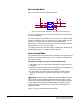
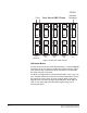
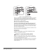
Figure 3-6 shows the non-isolated connection.
Figure 3-6: Non-Isolated Connection to Eclipse-32 GPI Connector
To cause an input to detect an active signal current must be sent from
the relevant input pin.
The external device should draw no current to cause an inactive input
and at least 5 mA to cause an active input. The opto-isolator drive line
contains a 1.5 kOhm resistor to limit the current through the
opto-isolator. It is therefore possible to connect the input pins directly
to a ground pin to cause an active input.
The voltage level at the external input pin should not be allowed to go
below ground or above +6 V with respect to ground.
Opto-Isolated Mode
If required the Eclipse-32 matrix can be operated in fully opto-isolated
mode. The unit must be taken out of service and powered down before
this change is made.
To operate the Eclipse-32 matrix in opto-isolated mode
1. If the Eclipse-32 unit is connected to AC power, disconnect it from
AC power.
2. Remove the top cover of the Eclipse-32 matrix by unscrewing the 12
M3 x 6 flat screws and lifting the cover upwards.
3. On the internal circuit board, move the jumper located under the
heading “J6” from pins 2-3 (marked “INT”) to pins 1-2 (marked
“ISO”).
Warning: A circuit board’s components include CMOS chips that
are sensitive to static electricity. Before touching the matrix’s circuit
board touch a grounded metal object, such as any unpainted surface
on the matrix, to dissipate static electricity.When handling a circuit
board, be careful not to bend any of the board’s connector pins or
component leads.
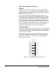
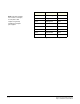
Figure 3-7 shows the opto-isolated connection.
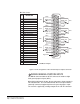
INPUT 1
EXTERNAL INPUT 2
INPUT 2
R29 1.5K
R30 1.5K
U
MOCD207-M
1
3
2
4
8
7
6
5
EXTERNAL INPUT 1
R
33K2
+3V3
R
33K2
+3V3
+3V3