
Instruction manual


Clear-Com Communication Systems
Eclipse-32 Matrix Instruction Manual
3-4
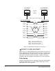
Figure 3-2: Wiring Matrix to Analog Panel Using RJ-45
WIRING TO 4-WIRE EQUIPMENT
Eclipse-32 uses a 2-pair analog wiring scheme between the matrix and
4-wire equipment. The wiring scheme shown in Figure 3-3 below is for
4-wire equipment with an RJ-45 connector. For 4-wire equipment with
other types of connector the pin connections should be changed in
accordance with the installation specification for the 4-wire equipment.
2-Pair Analog
Two-pair analog wiring to 4-wire equipment is done with shielded CAT5
RJ-45 cable if CAT5 cable is used or another suitable type of cable
depending on the 4-wire equipment.
RJ-45 CONNECTOR
AT MATRIX PORT
RJ-45 CONNECTOR ON
PANEL OR INTERFACE
Matrix Frame RJ-45 Pin Numbers
Shielded category-5 cables wired pin-to-pin
Panel RJ-45 Pin Numbers
Pair 2
Pair 1
Pair 3
Pair 4
RS-422 Input +
(into Matrix)
RS-422 Input –
(into Matrix)
Audio Input +
(into Matrix)
Audio Output +
(from Matrix)
Audio Output –
(from Matrix)
Audio Input –
(into Matrix)
RS-422 Output +
(from Matrix)
RS-422 Output –
(from Matrix)
1
2
3
5
6
7
1
2
6
7
8
4
3
4
5
8
RS-422 Output +
(from panel)
RS-422 Output –
(from panel)
Audio Output +
(from panel)
Audio Input +
(into panel)
Audio Input –
(into panel)
Audio Output –
(from panel)
RS-422 Input +
(into panel)
RS-422 Input –
(into panel)
Pair 1 Audio output from Matrix to panel
Pair 2 RS-422 data input from panel to Matrix
Pair 3 Audio input from panel to Matrix
Pair 4 RS-422 data output from Matrix to panel
8
7
65
4
3
2
1
8
7
6
5
4
3
2
1
Views from
front of
connectors
3