
Instruction manual


Clear-Com Communication Systems
Eclipse-32 Matrix Instruction Manual
2-5
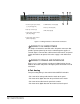
Figure 2-3: Rear Panel of an Eclipse-32 Matrix
CONNECTING TO AC POWER
An Eclipse-32 matrix’s rear panel contains two IEC AC power input
sockets for connecting AC mains power to the two power supplies.
Each IEC socket connects cable to one power supply, operating at an
input voltage of 100 to 240 volts, between 50 and 60 hertz.
CONNECTING TO PANELS AND INTERFACES
An Eclipse-32 matrix’s rear panel contains 36 RJ-45 sockets for
connecting the matrix to remote intercom panels and interfaces. These
sockets are often called “ports”. Each port socket is given a number on
the rear-panel for easy identification.
All ports contain a voice detection mechanism (“VOX”) that is
programmed from the Eclipse Configuration System software. VOX
detection allows the panel operator to know when the audio on a
particular channel has exceeded a threshold. This is particularly useful
for channels that are inactive periodically, so that the panel operator is
visually cued in the software when audio appears on the line.
Note: A shielded cable should be used.
CONNECTING TO GENERAL-PURPOSE OUT-
PUTS
The male 25-pin D-type socket labeled “GP OUT” allows the
Eclipse-32 matrix to be connected to eight general purpose outputs
(GPOs). General-purpose outputs are single-pole double-throw relays
with contact ratings of 30 VDC (volts direct current) at 1 ampere.
1
2
3
4
5
6
7
1 Two IEC AC power input connectors,
(1 per power-supply unit )
2 RJ-45 port connectors (36)
3 General purpose outputs connector
(male, 25-pin, D-type)
4 General purpose inputs connector
(female, 25-pin, D-type)
5 GPI/RLY interface connector (RJ-45)
6 Base loop connector (RJ-45)
7 LAN connector (RJ-45)
1
2
3
Note: General Purpose
Outputs are also referred to
as “relays.”