
Instruction manual


Clear-Com Communication Systems
Eclipse-32 Matrix Instruction Manual
2-3
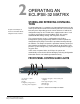
POWER SUPPLY ALARM LIGHTS (1 AND 2)
An Eclipse-32 matrix has two internal power supply units. One power
supply unit can power an entire matrix; the second unit provides a
backup in case of an equipment failure.
In addition, the two supplies have separate IEC connectors to AC
mains power, and are designed for completely automatic and
transparent changeover between supplies in the event of an outage on
one of the AC mains circuits.
The front-panel alarm lights do not illuminate under normal operating
conditions.
The following conditions cause a power-supply alarm light to
illuminate:
• If any of the voltages produced by the first power supply unit fall
below normal levels.
• If any of the voltages produced by the second power supply unit fall
below normal levels.
Once the power-supply fault condition is no longer present, the
power-supply alarm light goes out.
LAN STATUS LIGHTS
When a local area network is connected to the matrix’s LAN port, the
LAN UP light steadily illuminates to indicate that the Eclipse-32 matrix
is connected to a local area network. The Rx light flashes when data is
being received.
PORT STATUS LIGHTS
Each port status light corresponds to an RJ-45 connector on the
matrix’s rear panel to which an external device, such as an intercom
panel or interface, is connected. An illuminated port light indicates that
a device is connected to that port, and that communications are
running properly between the port and the matrix.
DEFAULT IP ADDRESS
From Eclipse 4.2 release onwards a factory default IP address
(172.16.2.100) is set up in the matrix firmware which will always be
available via an IP reset. This ensures that once the matrix firmware is
loaded it will always be possible to access the matrix via ethernet even
if the current IP address is not known.
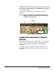
To carry out an IP reset it is necessary to remove the cover of the
Eclipse-32 in order to access the three reset switches positioned at the
front left of the main circuit board (viewed from the front of the unit)
shown in Figure 2-2. To carry out an IP reset press and hold the
6
7
8