
Instruction manual


Clear-Com Communication Systems
Eclipse-32 Matrix Instruction Manual
1-6
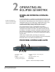
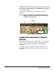
REAR-PANEL CONNECTORS (“PORTS”)
The Eclipse-32 matrix connects to remote devices such as intercom
panels, interfaces, general purpose inputs and outputs, local area
networks, and other matrices through its rear-panel hardware
connectors.
A rear-panel RJ-45 connector to which cable is connect to run from the
matrix to a panel or interface is called a “port”. Shielded category-5
cable is connected to a “port” to carry signals from the Eclipse-32
matrix to connected remote intercom panels or interfaces. Later
chapters of this manual discuss these connections in detail.
ECLIPSE CONFIGURATION SOFTWARE (ECS)
The Eclipse Configuration System (ECS) software controls the
operation of the matrix by sending electronic signals to the Eclipse-32
matrix, which then relays the signals to the remotely connected panels
and interfaces.
“Configuration Maps”—which are the operating parameters of
complete system setups can be created on the ECS computer. The
Eclipse Configuration System programming software stores the
created configurations on the computer’s hard disk using a relational
database which holds up to two gigabytes of configuration data and is
able to store over 100,000 complex system configurations. ECS can
then upload four complete configurations from the computer to the
Eclipse-32 matrix’s operational memory to retrieve and activate directly
from the matrix when needed.
The Eclipse Configuration System software runs on the following
versions of Windows: Windows 2000, Windows XP, Windows Server
2003 and Windows Vista (with restrictions). When running ECS on
Windows operating systems, the client and server can run on separate
machines connected over a network.
The Eclipse Configuration System can be used to create point-to-point
and fixed group or party-line communications among the connected
remote audio devices, assign a “label” to each port/panel, and inhibit or
enable features at any connected remote panel. The Eclipse
Configuration System can be set up to run on a client/server model
over a network allowing the matrix to be controlled remotely.
REMOTE INTERCOM PANELS AND ACCESSORY
PANELS
All analog intercom panels connect to the central matrix via shielded
category-5 cable terminated with RJ-45 connectors. Digital panels
connect to the central matrix through AES-6 or DIG-2 digital module
interfaces. Digital panels require double-shielded 24 AWG conductor
category-6 enhanced (CAT-6E) cable to connect to a DIG-2 interface
or coaxial cable to connect to the AES-6-CX rear card. For further