ECLIPSE-32 MATRIX INSTRUCTION MANUAL
Eclipse-32 Matrix Instruction Manual © 2007, 2009 Vitec Group Communications Ltd. All rights reserved. Part Number 810315Z Rev. 7 Vitec Group Communications LLC 850 Marina Village Parkway Alameda, CA 94501 U.S.A. Vitec Group Communications Ltd 7400 Beach Drive Cambridge Research Park Cambrideshire United Kingdom CB25 9TP The Vitec Group plc Beijing Representative Office Room 706, Tower B Derun Building, YongAn Dongli A No.3 Jianwai Ave., Chaoyang District Beijing, P.R.
CONTENTS INTRODUCTION . . . . . . . . . . . . . . . . . . . . . . . . . . . 1-1 The Eclipse-32 Matrix . . . . . . . . . . . . . . . . . . . . . . . . . . . . . . . . . . . . 1-1 Intelligent Linking . . . . . . . . . . . . . . . . . . . . . . . . . . . . . . . . . . . . . 1-2 High Speed Link . . . . . . . . . . . . . . . . . . . . . . . . . . . . . . . . . . . . . . 1-2 IFB Support . . . . . . . . . . . . . . . . . . . . . . . . . . . . . . . . . . . . . . . . 1-3 Powerful Programming Features . . . . . . .
Connecting to a Local Area Network . . . . . . . . . . . . . . . . . . . . . 2-7 INSTALLING AN ECLIPSE-32 MATRIX . . . . . . . . . 3-1 Verifying the Shipment . . . . . . . . . . . . . . . . . . . . . . . . . . . . . . . . . . . 3-1 Unpacking the System . . . . . . . . . . . . . . . . . . . . . . . . . . . . . . . . . . . 3-1 Installing the Eclipse-32 Matrix . . . . . . . . . . . . . . . . . . . . . . . . . . . . . 3-1 Battery Backup . . . . . . . . . . . . . . . . . . . . . . . . . . . . . . . . . . . . .
RETURN MATERIAL AUTHORIZATION POLICY . . . . . . . . . . . . . W-vi REPAIR POLICY . . . . . . . . . . . . . . . . . . . . . . . . . . . . . . . . . . . . .
iv Clear-Com Communication Systems Eclipse-32 Matrix Instruction Manual
IMPORTANT SAFETY INSTRUCTIONS Please read and follow these instructions before operating this product. 1. Read these instructions. 2. Keep these instructions. 3. Heed all warnings. 4. Follow all instructions. 5. Do not use this apparatus near water. 6. Clean only with dry cloth. 7. Do not block any ventilation openings. Install in accordance with the manufacturer’s instructions. 8.
CAUTION RISK OF ELECTRIC SHOCK DO NOT OPEN This symbol alerts you to the presence of uninsulated dangerous voltage within the product's enclosure that might be of sufficient magnitude to constitute a risk of electric shock. Do not open the product's case. This symbol informs you that important operating and maintenance instructions are included in the literature accompanying this product.
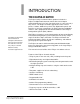
1 INTRODUCTION THE ECLIPSE-32 MATRIX The Eclipse family of communications products includes the Eclipse-32 digital matrix intercom, which offers 32 full-duplex communication ports, plus four extra 4-wire ports, in a one rack unit (1 RU) chassis.
INTELLIGENT LINKING An intelligent link may be used to connect an Eclipse-32 to other Eclipse-32, Eclipse Pico, Eclipse Median or Eclipse Omega matrices. Up to 15 matrices may be connected. The linking between matrices is via dedicated trunk lines between ports on the linked systems. This capability is in addition to the high-speed link which connects two Eclipse-32 matrices into one non-blocking 64-port system subject to the condition described below.
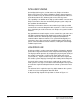
Figure 1-1: High Speed Link Operation IFB Support The High Speed Link supports the use of remote callers to IFB destinations between the linked systems. When a remote caller opens an audio path to an IFB destination the source for that IFB will be dimmed as normal. The High Speed Link will support the use of Local IFB where Assignment Panels can assign sources to an IFB locally. This option may be enabled in ECS (Advanced Settings > AP Panel Options > IFB Assignment).
• Forced listens (normally made routes) • Port I/O level control • Local and global ISO routes • Control labels The Eclipse-32 matrix allows TCP/IP access to the system for updates. The system may be accessed remotely for programming or to retrieve configurations. Up to four full-system configurations may be stored in the Eclipse-32 matrix, and an unlimited number of configurations may be backed up on a computer and downloaded to the matrix as needed.
ECLIPSE-32 APPLICATIONS The Eclipse-32 is the perfect solution for high-quality full-duplex communications requiring a moderate number of ports in a compact 1-RU form. With the ability to expand to 64 ports in 2 RU, tasks such as mobile production, small to mid-sized studio integration, and sports and performing facilities communications are easily realized. Intelligent linking to other Eclipse 32 and Eclipse Omega matrices adds to its ability to be the core of a comprehensive communications system.
REAR-PANEL CONNECTORS (“PORTS”) The Eclipse-32 matrix connects to remote devices such as intercom panels, interfaces, general purpose inputs and outputs, local area networks, and other matrices through its rear-panel hardware connectors. A rear-panel RJ-45 connector to which cable is connect to run from the matrix to a panel or interface is called a “port”. Shielded category-5 cable is connected to a “port” to carry signals from the Eclipse-32 matrix to connected remote intercom panels or interfaces.
details on connecting digital panels to the Eclipse-32 please refer to the appropriate product manual.
Each of these interfaces is described in its own manual. For a full description of the operation, installation, and maintenance of an interface, please refer to the individual manual for that interface.
2 OPERATING AN ECLIPSE-32 MATRIX STORING AND RETRIEVING CONFIGURATIONS No parts of the Eclipse -32 matrix are removable without taking the unit out of service. A “configuration map” is a complete set of operating parameters for the matrix system which includes talk and listen paths for each connected intercom panel.
1 PC CONNECTOR The female 9-pin D-type socket labeled “PC” connects the matrix to an external computer. 2 RESET BUTTON Pressing the reset button causes the matrix to stop its current activity and to restart. The same configuration that was active before the matrix was reset will be active after it is reset. During the reset, configuration information reloads to the matrix’s operational memory from its non-volatile memory and the matrix starts running again from the beginning.
6 POWER SUPPLY ALARM LIGHTS (1 AND 2) An Eclipse-32 matrix has two internal power supply units. One power supply unit can power an entire matrix; the second unit provides a backup in case of an equipment failure. In addition, the two supplies have separate IEC connectors to AC mains power, and are designed for completely automatic and transparent changeover between supplies in the event of an outage on one of the AC mains circuits.
rightmost two switches (nearest the side of the case) simultaneously and then press and release the ‘RESET’ button at the front of the unit, then release the internal switches. The unit will then be reset to the factory default IP address. The unit cover should be replace immediately the operation is completed. Warning: As the unit must be powered when resetting the IP address this operation should only be carried out by qualified service personnel.
2 1 3 5 4 6 7 Note: General Purpose Outputs are also referred to as “relays.
A general purpose output or “relay” is a switch that is controlled remotely. The relay is programmed in the Eclipse Configuration System software to close a contact whenever an intercom panel’s key is pressed. When the contact is closed, it completes an electronic circuit’s signal path so that a remote device, such as a light, is powered. A GPO can be programmed to mute a speaker, to turn on an applause light, to turn on a door lock, or to perform a variety of other functions.
The RLY-6 and GPI-6 cards connect to the GPI/RLY interface connector using shielded category-5 cable. For more information about the GPI-6 and RLY-6 cards, consult their respective manuals. Note: If this port is used a ferrite must be added to the socket end of the cable. A suitable ferrite is Würth Electronik part: 74271132. Note: A shielded cable should be used.
2-8 Clear-Com Communication Systems Eclipse-32 Matrix Instruction Manual
3 INSTALLING AN ECLIPSE-32 MATRIX VERIFYING THE SHIPMENT When the Eclipse-32 system is received inspect the boxes for shipping damage. Report any shipping damage to the carrier. The Eclipse-32 distributor is not responsible for shipping damage. Check the packing list and verify that every item on the list has been received. Save all packing materials in the event any items need to be returned.
A fully equipped Eclipse-32 matrix requires 100 to 240 VAC at 50 to 60 Hz with a maximum dissipation of 400 watts. BATTERY BACKUP The Eclipse-32 matrix is fitted with a non-rechargeable battery to maintain the system memory that stores the configuration maps and other system data in the event of power failure or the unit being switched off for a period of time. The Eclipse-32 battery is normally a 1/2AA 3V VARTA 6127-201-301 and would be fitted on shipment.
2 1 1 Two IEC AC power input connectors, (1 per power-supply unit ) 3 5 4 6 7 5 GPI/RLY interface connector (RJ-45) 6 Base loop connector (RJ-45) 2 RJ-45 port connectors (36) 7 LAN connector (RJ-45) 3 General purpose outputs connector (male, 25-pin, D-type) 4 General purpose inputs connector (female, 25-pin, D-type) Figure 3-1: Wiring Interfaces to Rear-Panel Connectors 1 WIRING TO AC MAINS POWER The Eclipse-32 matrix has two IEC mains AC power connectors that provide separate power inputs for t
RJ-45 CONNECTOR AT MATRIX PORT RJ-45 CONNECTOR ON PANEL OR INTERFACE 8 765 4 321 8 765 4 321 Views from front of connectors Shielded category-5 cables wired pin-to-pin Matrix Frame RJ-45 Pin Numbers RS-422 Input + (into Matrix) 1 RS-422 Input – (into Matrix) 2 Audio Input + (into Matrix) 3 Audio Output + (from Matrix) 4 Audio Output – (from Matrix) 5 Audio Input – (into Matrix) 6 RS-422 Output + (from Matrix) 7 RS-422 Output – (from Matrix) 8 Panel RJ-45 Pin Numbers Pair 2 Pair 1 Pair
• Pair 1 is not used. • Pair 2 transmits digital data from the 4-wire equipment back to the matrix. • Pair 3 transmits audio from the 4-wire equipment to the matrix. • Pair 4 is not used.
Single-Pair Digital Single-pair digital wiring is accomplished with double-shielded 24 AWG conductor CAT-6E enhanced STP cable in the case of a DIG-2 interface or CAT5 cable for the AES-6-CX interface. Pair 1 transmits and receives multiplexed digital and analog between the matrix frame and the panel. Note: Ensure that the “select” switch on the panel’s rear is in the correct position for the intended use.
DB-25 Male Connector DESCRIPTION PIN 1 2 3 4 5 6 7 8 9 10 11 12 13 14 15 16 17 18 19 20 21 22 23 24 25 RELAY RELAY RELAY RELAY 1 1 1 2 Common Normally Closed Normally Open Common RELAY 2 Normally Closed RELAY 2 Normally Open RELAY 3 Common RELAY 3 Normally Closed RELAY 3 Normally Open RELAY 4 Common RELAY 4 Normally Closed RELAY 4 Normally Open GROUND RELAY 5 Common RELAY 5 Normally Closed RELAY 5 Normally Open RELAY 6 Common RELAY 6 Normally Closed RELAY 6 Normally Open RELAY 7 Common RELAY 7 Normally
Non-Isolated Mode Figure 3-6 shows the non-isolated connection. +3V3 +3V3 +3V3 R 33K2 R 33K2 U R29 1.5K EXTERNAL INPUT 1 R30 1 8 2 7 3 6 4 5 INPUT 1 INPUT 2 1.5K EXTERNAL INPUT 2 MOCD207-M Figure 3-6: Non-Isolated Connection to Eclipse-32 GPI Connector To cause an input to detect an active signal current must be sent from the relevant input pin. The external device should draw no current to cause an inactive input and at least 5 mA to cause an active input.
U EXTVIN+ 7-24V 8 + C 10uF_25V D BYG22D VIN VOUT LM78L05ACM 1 +3V3 + +3V3 R 33K2 C 10uF_10V R 33K2 U R29 1.5K EXTVIN- 1 8 EXTERNAL INPUT 1 2 7 3 6 R30 EXTERNAL INPUT 2 INPUT 1 INPUT 2 1.5K 4 5 MOCD207-M Figure 3-7: Opto-Isolated Connection to Eclipse-32 GPI Connector In this mode, a DC voltage of between 7 and 24 volts is required at the EXTVIN+ pin with relation to the EXTVIN– pin. To cause an input to detect an active signal current must be sent from the relevant input pin.
Pin Assignments for General-Purpose Inputs Connector DB-25 Female Connector PIN 1 2 3 4 5 6 7 8 9 10 11 12 13 14 15 16 17 18 19 20 21 22 23 24 25 DESCRIPTION Logic Input 1 Logic Input 2 Logic Input 3 Logic Input 4 N/A N/A N/A N/A Ground Ground Ground Ground Ground Logic Input 5 Logic Input 6 Logic Input 7 Logic Input 8 N/A N/A N/A N/A Voltage In+ Voltage In+ Voltage InVoltage In- Logic Input 1 1 Logic Input 2 2 Logic Input 3 3 Logic Input 4 4 14 Logic Input 5 15 Logic Input 6 16 Logic Input 7
The following sections give an overview of the wiring of these interfaces. For more detailed discussion of wiring of interfaces in general, see the manual Eclipse Matrix Installation Manual (part 810298Z). RLY-6 Interface Wiring The RLY-6 relay interface module connects up to six programmable relays to the matrix so that each relay is directly controlled from the matrix. Multiple RLY-6 interfaces can be daisy chained to provide connection of up to 60 relays to the matrix.
Ports Rear View of IMF-3 Frame GPI/RLY Interface Connector RJ-45 RJ-45 RJ-45 RJ-45 RJ-45 DB-9 DB-9 DB-9 DB-9 DB-9 RJ-45 RJ-45 RJ-45 RJ-45 RJ-45 DB-9 DB-9 DB-9 DB-9 DB-9 Other Interfaces RLY-6 #2 RLY-6 #1 GPI-6 #2 GPI-6 #1 Figure 3-9: Rear View of IMF-3 Frame To External Device To connect external devices to the RLY-6 interface, use the two DB-9M connectors on the rear cable assembly panel for the interface.
RLY-6 I/O DB-9M 1 6 #1/4 Normally Closed #1/4 COM 2 #1/4 Normally Open #2/5 Normally Closed 7 3 8 #2/5 COM #2/5 Normally Open 4 9 #3/6 Normally Closed #3/6 COM 5 #3/6 Normally Open Figure 3-10: RLY-6 Interface DB-9M Connector Pinout IMF-102 Interface Module Frame Wiring The wiring of a RLY-6 interface that is placed in an IMF-102 interface frame is the same as the wiring for a RLY-6 interface placed in an IMF-3 interface frame.
IMF-3 Interface Module Frame Wiring To Matrix To connect the GPI-6 to the matrix, plug one end of an RJ-45 cable (eight wires with no reversal) into the GPI/RLY INTERFACE connector on the back of the matrix. Plug the other end into the top RJ-45 (CH. A MATRIX) connector for the GPI-6. To connect an additional GPI-6 interface, plug one end of a short RJ-45 cable into the lower RJ-45 (CH. B MATRIX) for the first GPI-6. Then, plug the other end into the top RJ-45 (CH.
GPI-6 I/O DB-9M GPI-6 I/O DB-9M 1 1 6 6 2 2 7 7 3 3 8 8 4 X 9 4 5 X X 9 5 X Figure 3-12: GPI-6 Application Examples Figure 3-11 and Figure 3-12 show how to connect switches or contacts using the power source provided by the GPI-6 module or powering switches from external sources. Each input can be wired to be isolated from each other as a further variation.
Cable end 1 NOTE: If the ECS computer does not have a serial port, and only offers USB, adapters are generally available from computer parts suppliers.
8 WIRING TO A LOCAL AREA NETWORK The LAN connector has standard Ethernet pin assignments.
WIRING TO A COMPUTER The DB-9 connector labeled “PC” connects the Eclipse-32 matrix to an external computer. This connector is located on the Eclipse-32 matrix’s front panel. To connect a computer to the matrix, run cable from the matrix’s “PC” connector to the PC’s serial port. The maximum recommended length of the cable is approximately 10 feet (3 meters). A computer has either a 9-pin serial port or a 25-pin serial port. Figure 3-14 shows the wiring for a 9-pin port.
1 14 2 Computer Serial Port DB-25F Cable Connector Transmit (TXD) 1 6 15 3 Receive (RXD) Transmit (TXD) Eclipse Frame "IBM-PC RS-232" DB-9M Cable Connector 2 7 16 4 Receive (RXD) 3 8 17 4 5 9 18 Ground (GND) 6 5 19 7 20 8 21 9 22 10 23 11 24 12 25 13 Figure 3-15: Wiring the Matrix DB-9M to a DB-25F Computer Serial Port Connector Clear-Com Communication Systems Eclipse-32 Matrix Instruction Manual 3-19
3-20 Clear-Com Communication Systems Eclipse-32 Matrix Instruction Manual
4 MAINTENANCE RECOMMENDED SPARE PARTS To facilitate quick repair of the system with minimum downtime, Clear-Com recommends keeping the following spare system components in good working condition at all times: • One of each type of intercom panel in the system • One of each type of interface in the system Due to the complexity of the system, field service generally should be limited to isolating the specific component of the system with the problem.
4-2 Clear-Com Communication Systems Eclipse-32 Matrix Instruction Manual
5 SPECIFICATIONS dBu is an absolute measurement. 0 dBu is referenced to 0.775 volts RMS General Height 44 mm or 1.75 inches (1 RU) Width 482 mm (19 inches) Depth 300 mm (12 inches) Weight 5 kg max. Power Consumption 60W Max.
Network 10/100 Base-T Ethernet maximum distance: 100 meters connector RJ-45 Serial PC RS-232 Baud rate: 57600 Maximum distance: 10 meters Number of ports: 1 Connector: 9-way D-type socket on front System Programming Crosspoint Level Control Input Level Control Output Level Control VOX Input Detection Threshold 0.355 dB steps 0.355 dB steps 0.
Supported Panels and Interfaces: ICS-1008, ICS-1016, ICS-52, ICS-92, ICS-62, ICS-102, IMF-102, ICS-2003, i-Station family, XPL-22, XPL-12, IMF-3, TEL-14, CCI-22, FOR-22, RLY-6, GPI-6, DIG-2, AES-6, 4000 Series II Panels, V-Series Panels. Notice About Specifications While Clear-Com makes every attempt to maintain the accuracy of the information contained in its product manuals, that information is subject to change without notice.
5-4 Clear-Com Communication Systems Eclipse-32 Matrix Instruction Manual
6 GLOSSARY Analog Port Any of the Eclipse matrix’s analog input/output RJ-45 connectors that are used to connect cable from the matrix to panels and interfaces. Each “port” connects to a separate audio channel in the matrix intercom system. Bus A bus is the channel or path between the components in the matrix along which electrical signals flow to carry information from one component to the next. In the Eclipse matrix the bus is located in the etched surface of the midplane.
Fiber-optic Cable A fiber-optic cable consists of a glass core covered with a reflective material called “cladding” and several layers of buffer coating to protect the cable from the environment. A laser sends light pulses through the glass core to the other end of the cable. FreeSpeak Digital wireless communications product. Sold under the FreeSpeak name in Europe and Asia and CellCom in USA. Full Duplex Refers to transmission of signals in two directions simultaneously. IFB “Interruptible Foldback”.
by manufacturers. Single-mode fiber evolved as production methods improved. Multiplexing The process by which two or more signals are transmitted over a single communications channel. Examples include time division and wavelength division multiplexing. Nanometer (nm) Common unit of measure for wavelength. One billionth of a meter. Non-volatile Memory Data stored in the CPU’s firmware (ROM) that is not lost when the power is turned off.
VOX In the Eclipse system, when audio at a panel exceeds a threshold, a light switches on at the panel’s port card to visually cue the operator. The threshold level is set in the Eclipse Configuration Software. V-Series Communications panels used with Eclipse systems providing advanced facilities. Available in rack mount and desktop formats. Wavelength-division Multiplexing (WDM) A method of multiplexing optical signals developed for use on fiber-optic cable.
ECLIPSE MANUALS The following manuals are available covering Eclipse products and accessories.
Eclipse FIM-102 Fiber Interface Instruction Manual - 810319Z Eclipse FIM-108 Fiber Interface Instruction Manual - 810291Z Eclipse 4000 Series II Panels Installation Guide - STA0530Z Eclipse 4000 Series II Panels User Guide - STA0531Z Eclipse ICS 1008E/1016E Panels Instruction Manual - 810404Z Eclipse ICS 102/62 Panels Instruction Manual - 810302Z Eclipse ICS 2003 Panel Instruction Manual 810303Z Eclipse ICS 92/52 Panels Instruction Manual - 810301Z Eclipse i-Station Instruction Manual - 810305Z Eclipse ICS-
LIMITED WARRANTY This document details the Clear-Com Standard Limited Warranty for all new products for sale within all regions with the exception of Military, Aerospace, and Government (MAG). EXCEPT AS SET FORTH HEREIN ("LIMITED WARRANTY"), CLEAR-COM MAKES NO OTHER WARRANTIES, EXPRESS, IMPLIED OR STATUTORY, INCLUDING WITHOUT LIMITATION ANY WARRANTIES OF MERCHANTABILITY, NONINFRINGEMENT OF THIRD PARTY RIGHTS, OR FITNESS FOR A PARTICULAR PURPOSE, ALL OF WHICH ARE EXPRESSLY DISCLAIMED. 1.
(5) All software products, including Concert (Client and Server), ECS, Production Maestro and Logic Maestro are warranted for one year and shall substantially conform to published specifications. The media on which the Software is furnished is warranted to be free of defects in material and workmanship (under normal use) for a period of one year. (6) Any Clear-Com products that are listed within the last time buy period have the same Limited Warranty for their type 1.i 1 - 1.i.5 as above.
h) Software Upgrades i) Software Upgrades include new Features and/or Functional Enhancements and are not included as part of the Standard Warranty but may be purchased at the published rates. ii) Note: In the absence of a Software Update containing a program correction and no available workaround to mitigate the problem, at the discretion of Service, Sales, Engineering, or Product Management, the Customer may be provided a Software Upgrade under warranty. 2. Exclusions.
iv Clear-Com Communication Systems Standard Limited Warranty
TECHNICAL SUPPORT & REPAIR POLICY NOVEMBER 1, 2008 In order to ensure that your experience with Clear-Com and our World Class products is as beneficial, effective and efficient as possible, we would like to define the policies and share some "best practices" that can accelerate any problem solving processes which we may find necessary and to enhance your customer service experience. Our Technical Support, Return Material Authorization, and Repair Policies are set forth below.
Days: Tel: Email: iii) Asia-Pacific: Hours: Days: Tel: Email: Monday - Friday +49 40 853 999 700 TechnicalSupportEMEA@vitecgroup.com 0800 - 1700 Pacific Time Monday - Friday +1 510 337 6600 CustomerServicesAPAC@vitecgroup.com d) Email Technical Support is available for all Clear-Com branded products free of charge for the life of the product, or two years after a product has been classified as obsolete, whichever comes first.
d) Damaged equipment will be repaired at the Customer's expense. e) Returns are subject to a 15% restocking fee. f) Advance Warranty Replacements (AWRs); i) During the first 30 days of the Standard Warranty Period: Once the equipment fault has been verified by Clear-Com or its authorized representative, Clear-Com will ship a new replacement product.
vii) Note: Shipping charges, including duties, taxes, and insurance (optional), to Clear-Com's factory is the responsibility of the Customer. Shipping AWRs from Clear-Com is at Clear-Com's expense (normal ground or international economy delivery). Requests for expedited shipping (E.g. "Next-Day Air") and insurance are the responsibility of the Customer.
the cost of repair, the Customer may elect to return the product to the factory for an estimate. The Customer is responsible for shipping costs both to and from the factory in the event they choose not to accept the estimate. v) The Customer must provide either a purchase order for the repair work, or will be required to make an advance payment (as a debit against the Dealer's line of credit, or credit card) prior to the repaired product being returned to the Customer.