
Instruction manual


ECLIPSE OMEGA MATRIX INSTRUCTION MANUAL
5-15
To cause an input to detect an active signal, you must send current from the
relevant input pin.
The external device should draw no current to cause an inactive input and at least
5 mA to cause an active input. The opto-isolator drive line contains a 1.5 kOhm
resistor to limit the current through the opto-isolator. You can therefore connect
the input pins directly to a ground pin to cause an active input.
The voltage level at the external input pin should not be allowed to go below
ground or above +6 V with respect to ground.
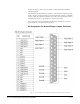
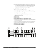
Pin Assignments for General-Purpose Inputs Connector
Figure 5-12: Pin Assignments for Eclipse Omega General-Purpose Inputs Connector