
Instruction manual


ECLIPSE OMEGA INSTRUCTION MANUAL
5-14
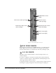
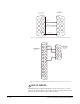
To select a mode, move the J1 jumper on the CPU rear card to one of two
positions. (The J1 jumper is located on the inner-matrix side of the DB-25
connector.)
• For opto-isolated mode, fit the J1 jumper across pins 1 and 2.
• For non-isolated mode, fit the J1 jumper across pins 2 and 3.
Note: It is recommended that you set the connector to the fully opto-isolated
mode.
Opto-Isolated Mode
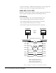
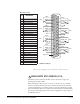
Figure 5-10 shows the opto-isolated connection.
Figure 5-10: Opto-Isolated Connection to Eclipse Omega GPI Connector
In this mode, a DC voltage of between 7 and 24 volts is required at the
EXTVIN+ pin with relation to the EXTVIN– pin. To cause an input to detect
an active signal, you must send current from the relevant input pin.
The external device should draw no current to cause an inactive input and at least
5 mA to cause an active input. The opto-isolator drive line contains a 1.5 kOhm
resistor to limit the current through the opto-isolator. You can therefore connect
the input pins directly to the EXTVIN– level to cause an active input.
The voltage level at the external input pin should not be allowed to go below
EXTVIN– or above +6 V with respect to EXTVIN–.
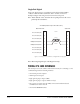
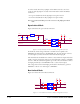
Non-Isolated Mode
Figure 5-11 shows the non-isolated connection.
Figure 5-11: Non-Isolated Connection to Eclipse Omega GPI Connector
+
C
10uF_10V
D
BYG22D
+
C
10uF_25V
INPUT 1EXTVIN-
EXTERNAL INPUT 2
EXTVIN+
INPUT 2
R29 1.5K
U
LM78L05ACM
VIN
8
VOUT
1
7-24V
R30 1.5K
U
MOCD207-M
1
3
2
4
8
7
6
5
EXTERNAL INPUT 1
R
33K2
+3V3
R
33K2
+3V3
INPUT 1
EXTERNAL INPUT 2
INPUT 2
R29 1.5K
R30 1.5K
U
MOCD207-M
1
3
2
4
8
7
6
5
EXTERNAL INPUT 1
R
33K2
+3V3
R
33K2
+3V3
+3V3