
Instruction manual


ECLIPSE OMEGA MATRIX INSTRUCTION MANUAL
5-13
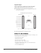
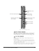
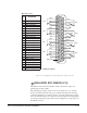
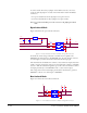
Figure 5-9: Pin Configuration of the General-Purpose Outputs Connector
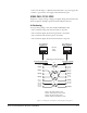
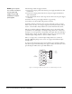
GENERAL-PURPOSE INPUTS CONNECTOR (GP IN)
The DB-25 connector labeled “GP IN” connects the matrix to eight local
general-purpose inputs (GPIs).
The general-purpose inputs operate in one of two modes: the “opto-isolated”
mode or the unisolated mode. The opto-isolated mode requires the externally
connected equipment to provide the current to power the general-purpose input.
The non-isolated mode does not require that the externally connected equipment
powers the general-purpose input. The current is supplied by a voltage output on
the GP IN connector.
1
2
3
4
5
6
7
8
9
10
11
12
13
14
15
16
17
18
19
20
21
22
23
24
25
Digital Ground
PIN
DESCRIPTION
1
2
3
4
RELAY 1 Common
RELAY 1 Normally Closed
RELAY 1 Normally Open
RELAY 2 Common
RELAY 2 Normally Closed
RELAY 2 Normally Open
RELAY 3 Common
RELAY 3 Normally Closed
RELAY 3 Normally Open
30 VDC at 1 Ampere
Common
Normally Open
Normally Closed
Common
Normally Open
Normally Closed
Common
Normally Open
Normally Closed
Common
Normally Open
Normally Closed
Common
Normally Open
Normally Closed
Common
Normally Open
Normally Closed
Common
Normally Open
Normally Closed
Common
Normally Open
Normally Closed
RELAY 1
RELAY 2
RELAY 3
RELAY 4
RELAY 5
RELAY 6
RELAY 7
RELAY 8
RELAY 4 Common
RELAY 4 Normally Closed
RELAY 4 Normally Open
GROUND
RELAY 5 Common
RELAY 5 Normally Closed
RELAY 5 Normally Open
RELAY 6 Common
RELAY 6 Normally Closed
5
6
7
8
9
10
11
12
13
14
16
17
18
19
20
21
22
23
24
25
15
RELAY 6 Normally Open
RELAY 7 Common
RELAY 7 Normally Open
RELAY 7 Normally Closed
RELAY 8 Common
RELAY 8 Normally Closed
RELAY 8 Normally Open
DB-25 Male Connector
5