
Instruction manual

ECLIPSE OMEGA MATRIX INSTRUCTION MANUAL
5-11
The following conditions trigger an alarm:
1. If any of the voltages produced by the first power supply unit fall below their
normal levels.
2. If any of the voltages produced by the second power supply unit fall below
their normal levels.
3. If an external alarm circuit or other logic circuit connected to the power supply
is activated.
4. If either of the two power-supply unit fans stop operating.
5. If software on a master CPU card generates an alarm.
An alarm condition activates the relay contacts connected to pins 4, 5, and 9.
These contacts are “dry,” (no voltage is supplied to them by the matrix) and are
rated at 1 A at 24 VDC. They should not be used for AC mains line current.
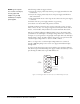
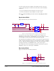
Pins are provided for adding an additional alarm source to the matrix’s alarm
system. Pin 6 is an alarm input to the Eclipse Omega matrix. It is connected to
the input of a 3.3 V logic device. A logic high on this input will cause the Eclipse
Omega matrix to detect an alarm condition. A logic low or an open circuit will
cause the Eclipse Omega matrix to detect no alarm condition.
Pin 1 is a voltage source out of the Eclipse Omega matrix. It is connected
through a 10Kohm pull-up resistor to the +5 V supply rail inside the Eclipse
Omega matrix.
A contact closure placed across pins 1 and 6 will also cause an alarm condition.
The alarm outputs of the PSU-101 power supply could be wired directly to these
pins allowing the CPU card to report PSU failures also.
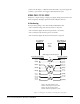
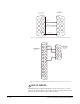
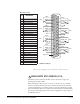
Figure 5-7: Wiring the Alarm I/O Connector to an Alarm Relay Connector
1
2
9
8
7
6
5
4
3
1
2
3
4
Relay Normally Closed
Relay Wiper/Common
Relay Normally Open
To Ala rm
To Ala rm
Eclipse
"Alarm I/O" DB-9F
Connector
PSU-101
"Alarm Relay"
Connector
NOTE: If your computer
does not have a serial port,
and only offers USB,
adapters are generally
available from computer
parts suppliers.