
Instruction manual


ECLIPSE OMEGA MATRIX INSTRUCTION MANUAL
5-9
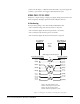
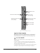
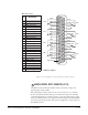
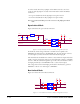
Figure 5-4: CPU Card Interface Connectors
GPI/RLY INTERFACE CONNECTOR
For wiring pinout information for GPI/RLY interfaces, see the Relay Interface
Module (RLY-6) Instruction Manual and the General Purpose Inputs (GPI-6)
Instruction Manual in the set of manuals that came with your Eclipse system.
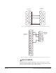
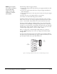
RS-232 DB-9 CONNECTOR
The DB-9 connector labeled “RS-232” connects the Eclipse matrix to an
external computer.
To connect a computer to the matrix, run cable from the matrix’s “RS-232”
connector to the PC’s serial port. The maximum recommended length of the
cable is approximately 10 feet (3 meters).
A computer has either a 9-pin serial port or a 25-pin serial port. Figure 5-5 shows
the wiring for a 9-pin port. Figure 5-6 shows the wiring for a 25-pin port.
1
2
3
4
5
6
7
GPI/RLY Interface Connector
(RJ-45)
Alarm I/O Connector
(female 9-pin D-type)
General Purpose Inputs Connector
(female 25-pin D-type)
LAN 1 Connector (RJ-45)
LAN 2 Connector (RJ-45)
RS-232 Connector (female 9-pin D-type)
General Purpose Outputs Connector
(male 25-pin D-type)
1
2