
Instruction manual


ECLIPSE OMEGA INSTRUCTION MANUAL
5-8
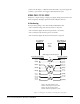
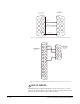
Single-Pair Digital
Single-pair digital wiring is accomplished with double-shielded 24 AWG
conductor CAT-6E enhanced STP cable. Pair 1 transmits and receives
multiplexed digital and analog between the matrix and the panel.
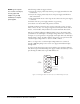
Note: Ensure that the “select” switch on the rear of the panel is in the correct
position for the intended use.
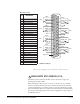
Figure 5-3: Wiring from the Matrix to a Digital Panel Using RJ-45
Note: This wiring diagram refers to the Digi-2 unit only.
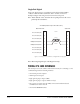
WIRING CPU CARD INTERFACES
The central processor unit (CPU) card holds the circuitry for connecting to, and
communicating with, the following interfaces:
• An external personal computer
• Alarm inputs and outputs
• Eight general purpose inputs (GPIs)
• Eight general purpose outputs (GPOs or relays)
• Two separate local area network (LAN) connections for Ethernet-based
communication with a network
• An external GPI/RLY interface
Pair 2
Pair 1
Pair 3
Pair 4
1
2
3
4
5
6
7
8
1
2
3
4
5
6
7
8
Matrix Frame End
ATT-T568B (Modular Jumpers Wired One to One)
Station En
d
No Connection (NC)
No Connection (NC)
No Connection (NC)
M
ultiplexed Data/Audio
M
ultiplexed Data/Audio
No Connection (NC)
No Connection (NC)
No Connection (NC)