
Instruction manual


ECLIPSE OMEGA MATRIX INSTRUCTION MANUAL
5-7
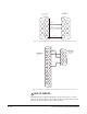
connect each AC input to a different mains AC branch, one power supply will
continue to operate if the other supply’s mains AC branch opens.
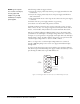
WIRING PANELS TO THE MATRIX
Eclipse uses a 4-pair (analog) or single-pair (digital) wiring scheme between the
matrix and panels. All Eclipse panels have built-in RJ-45 connectors.
4-Pair Analog
Four-pair analog wiring is done with shielded CAT5 RJ-45 cable.
• Pair 1 transmits analog audio from the matrix to the panel.
• Pair 2 transmits digital data from the panel back to the matrix.
• Pair 3 transmits audio from the panel to the matrix.
• Pair 4 transmits digital data from the matrix back to the panel.
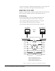
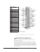
Figure 5-2: Wiring from the Matrix to an Analog Panel Using RJ-45
RJ-45 CONNECTOR
AT MATRIX PORT
RJ-45 CONNECTOR ON
STATION OR INTERFACE
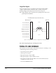
Matrix Frame RJ-45 Pin Numbers
Shielded category-5 cables wired pin-to-pin
Station RJ-45 Pin Numbers
Pair 2
Pair 1
Pair 3
Pair 4
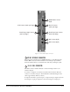
RS-422 Input +
(into Matrix)
RS-422 Input
(into Matrix)
Audio Input +
(into Matrix)
Audio Output +
(from Matrix)
Audio Output
(from Matrix)
Audio Input
(into Matrix)
RS-422 Output +
(from Matrix)
RS-422 Output
(from Matrix)
1
2
3
5
6
7
1
2
6
7
8
4
3
4
5
8
RS-422 Output +
(from station)
RS-422 Output
(from station)
Audio Output +
(from station)
Audio Input +
(into station)
Audio Input
(into station)
Audio Output
(from station)
RS-422 Input +
(into station)
RS-422 Input
(into station)
Pair 1 Audio output from Matrix to station
Pair 2 RS-422 data input from station to Matrix
Pair 3 Audio input from station to Matrix
Pair 4 RS-422 data output from Matrix to station
8
7
65
4
3
2
1
8
7
6
5
4
3
2
1
Views from
front of
connectors