
Instruction manual


ECLIPSE OMEGA MATRIX INSTRUCTION MANUAL
5-3
• Shielded category-5 cables to connect to panels and interfaces.
INSTALLING THE ECLIPSE OMEGA MATRIX
The following overview gives you a summary of the steps required to install an
Eclipse Omega matrix. More detailed information on each step is provided in the
sections that follow.
To install an Eclipse Omega matrix:
1. Remove the Eclipse Omega matrix chassis from its shipping carton.
2. Leave at least 2 inches (51 mm) of clearance on all sides of the matrix chassis to
ensure proper airflow. Do not block ventilation vents.
3. Check the position of circuit cards, power supplies, and rear-connector panels.
Later sections in this chapter give more information on these items.
4. Apply AC power to the unit. The unit has two separate AC power entry
connectors for the two separate power supplies in the system.
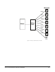
INSTALLING POWER SUPPLIES
The Eclipse Omega system’s DC power supplies run on AC mains power. Two
identical Euro Cassette power supplies are provided to ensure that every matrix
will have redundant power—that is, to ensure that the matrix will continue to
operate even if one supply output fails.
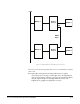
Each of the power supplies must be connected to a dedicated branch of AC
mains power. The matrix will continue to operate even if one of the AC power
branches fails.
Clear-Com ships each matrix with power supplies already installed. When you
receive the matrix, connect the power supplies to AC mains power using the IEC
power connectors on the matrix’s rear panel.
A fully equipped Eclipse Omega matrix (13 port cards, 2 expansion cards)
requires 100 to 240 VAC at 40 to 50 Hz with a maximum dissipation of 400 W.
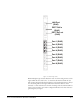
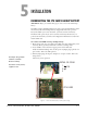
INSTALLING THE REAR RJ-45 CONNECTOR PANELS
The matrix’s rear panel is constructed of modular, individually-installable
connector panels. Each port or expansion card has a corresponding
rear-connector panel. Each MVX connector panel holds 16 RJ-45 connectors.
Clear-Com ships each matrix with the required number of rear-connector panels
already installed. Blank rear panels fill unused card slots.
INSTALLING REAR RJ-45 CONNECTOR PANELS IN
THE FIELD
Installing or removing a rear panel from the matrix is a simple procedure,
allowing you to easily customize the matrix to your operating environment.
To add a rear panel to the matrix: