
Instruction manual


ECLIPSE OMEGA MATRIX INSTRUCTION MANUAL
3-6
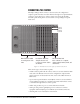
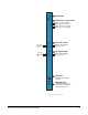
The fiber optic cable for the primary and secondary circuits are plugged into the
appropriate ports.
Eye Safety
This laser based single mode transceiver is a Class 1 product. It complies with
IEC 60825-1/A2:2001 and FDA performance standards for laser products (21
CFR 1040.10 and 1040.11) except for deviations pursuant to Laser Notice 50,
dated July 26, 2001.
Note: The order of the fiber optic cable connections is reversed between the front
and rear panels. On the front panel the primary connection is the upper set
of indicators but on the rear panel it is the lower connector. Similarly the
secondary connetion is the lower set of indicators on the front panel but the
upper connector on the rear panel. Care should be taken when connecting
or disconnecting the cables to ensure that they are connected correctly and
not reversed.
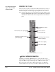
Note: Normally a protective plug is fitted to the fiber connector sockets to protect
them from damage or the entry of foregn materials. These should only be
removed in order to fit the fiber optic cable and replaced if the cable is
unplugged.
CONFIGURING A FIBER OPTIC CONNECTION
There are a number of ways that optical connections can be made between
systems depending on the level of redundancy required.
When a break occurs in the fiber ring, a solid red status light will be shown at the
fiber card downstream from the break and the link status LEDs may show amber.
Other fiber cards will intermittently show red, as the ring attempts to recover. If
the system layout is displayed by ECS the faulty links are shown in red.
In order to diagnose faults or switch between primary and secondary rings or
between primary and backup fiber linking cards the My Systems in ECS must be
used. Ensure that the current configuration is open and click on ‘Live Status’ in
the My Systems toolbar to display the current system state.
This will allow the operator to intevene to alter the system configuration as
required. For details of ECS please refer to the ECS instruction manual (part
number 810299).
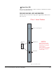
SIMPLEX FIBER CABLING
Single Card Set Redundancy
In this case each Matrix Frame contains one fiber-optic Linking card set . This is
shown as in Figure 3-3. This approach still affords fiber connection redundancy
since each rear card houses two fiber-optic transceivers.
In the absence of an Uninterruptible Power Supply this configuration will not
protect against loss of the node or Matrix Frame itself.