
Instruction manual


ECLIPSE OMEGA MATRIX INSTRUCTION MANUAL
2-17
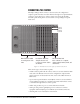
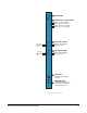
from the matrix by daisy-chaining the cards together. Each card has an IN and an
OUT connector for this purpose.
The RLY-6 and GPI-6 cards connect to the GPI/RLY interface connector using
shielded category-5 cable. For more information about the GPI-6 and RLY-6
cards, consult their respective manuals in the Eclipse Omega manual set.
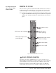
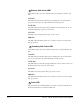
RS-232 CONNECTOR
The female 9-pin D-type socket labeled “RS-232” connects the CPU card to an
external computer.
ALARM I/O CONNECTOR
The female 9-pin D-type socket labeled “Alarm I/O” connects the Eclipse matrix
to an external alarm indicator, such as a light or buzzer and/or to an external
alarm source.
GENERAL-PURPOSE OUTPUTS CONNECTOR (“GP OUT”)
The male 25-pin D-type socket labeled “GP OUT” connects the CPU card to
eight general purpose outputs (GPOs). General-purpose outputs are single-pole
double-throw relays with contact ratings of 30 VDC (volts direct current) at 1
ampere.
A general purpose output or “relay” is a switch that you control remotely. You
program the relay in the ECS configuration program to close a contact whenever
an intercom panel’s key is pressed. When the contact is closed, it completes an
electronic circuit’s signal path so that a remote device, such as a light, is powered.
You can program a GPO to mute a speaker, to turn on an applause light, to turn
on a door lock, or to perform a variety of other functions. For example, to get the
attention of a panel operator working in a high-noise environment such as a
control booth, you can program a relay to switch on a light at his panel each time
he receives an incoming call, to ensure that he will not miss the call.
Note: If you use the GP-OUT port, you must fit the following filter between the
PROC-RCC socket and the cable:
CINCH FA-25PS/1 25W D-type in-line 1000pF filter
(UK supplier: Farnell 322-2676)
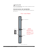
GENERAL-PURPOSE INPUTS CONNECTOR (“GP IN”)
The female 25-pin D-type socket labeled “GP IN” connects the Eclipse Omega
CPU card to eight general purpose inputs (GPIs).
You can connect an external logic device–such as an external foot switch, a
panel-mounted switch, or the logic output of some other device–to the “GP IN”
connector. When the external logic device is activated, it sends a control signal
into the matrix to perform one of several preset functions, such as turning an
2
3
4
5