
Instruction manual


ECLIPSE OMEGA MATRIX INSTRUCTION MANUAL
2-16
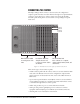
CONNECTING THE CPU CARD
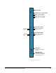
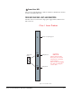
The rear-connector panel associated with the CPU card holds seven connectors,
as illustrated in Figure 6. The following sections describe each connector. The
Installation Chapter of this manual gives pin assignments for each connector.
Note: A matrix only requires one rear-panel CPU card, because whichever of the
two front-installed CPU cards is acting as master will work in conjunction
with this card. All other cards, however, require their own rear-connector
panel.
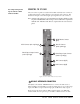
Figure 2-6: CPU Card’s Rear-Connector Panel
GPI-RLY INTERFACE CONNECTOR
The RJ-45 socket labeled “GPI/RLY Interface” connects the CPU card to a
GPI-6 or RLY-6 card. The GPI-6 provides six general-purpose opto-isolated logic
inputs. The RLY-6 card provides six single-pole, double-throw relay outputs.
Both card types mount in either an IMF-3 interface frame or an IMF-102
interface frame. You can operate up to ten GPI-6 or RLY-6 cards at one time
1
2
3
4
5
6
7
GPI/RLY Interface Connector
(RJ-45)
Alarm I/O Connector
(female 9-pin D-type)
General Purpose Inputs Connector
(female 25-pin D-type)
LAN 1 Connector (RJ-45)
LAN 2 Connector (RJ-45)
RS-232 Connector (male 9-pin D-type)
General Purpose Outputs Connector
(male 25-pin D-type)
1
You can precisely locate
a port with its column
and row number.