
Instruction manual


ECLIPSE OMEGA MATRIX INSTRUCTION MANUAL
2-15
CONNECTING THE MATRIX
The Eclipse Omega matrix connects to devices such as the configuration
computer, panels, interfaces, and other matrices through its rear-panel hardware
connectors, often called “ports.” These connectors are housed in modular
removable panels. Each panel is associated with a corresponding front-panel
circuit card.
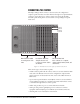
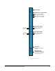
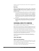
Figure 2-5: The Eclipse houses three types of rear-connector panels
There are five types of rear-connector panels:
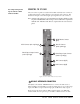
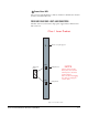
• A CPU-card rear panel holds the various connectors associated with the CPU
card, such as the RS-232 connector for the configuration computer. This
panel’s connectors are discussed in the next section, titled “Rear-Connector
CPU Card.”
• A port-card rear panel holds the sixteen RJ-45 connectors associated with its
corresponding front-panel port card. Intercom panels and interfaces connect
to the matrix through this rear-connector panel.
• A fiber card provides two ports to connect fiber network cables.
• An E-Que card provides eight RJ-45 ports for connection to wireless
equipment and three RJ-45 ports for DECT sync and LAN connections.
• A blank panel covers an unused slot in the matrix.
The CPU-Card Rear Panel
houses connectors for a computer,
computer network, interfaces, alarms, and
other matrices.
Port 1-1
Port 1-2
Port 1-3
Port 1-4
Port-Card Rear Panels have
16 RJ-45 connectors each,
to connect to intercom stations
and interfaces.
Blank Panels are installed
in unused portions of the
frame.