
Instruction manual


ECLIPSE OMEGA MATRIX INSTRUCTION MANUAL
2-10
POWER SUPPLY DESCRIPTION
Eclipse Omega has two Euro Cassette power supply units that you can easily
install or remove as needed. One power supply unit can power an entire matrix;
the second unit provides a backup in case of an equipment failure.
In addition, the two supplies have separate IEC connectors to AC mains power,
and are designed for completely automatic and transparent changeover between
supplies in the event of an outage on one of the AC mains circuits. For this
feature to work, each power supply should be connected to a different AC mains
branch.
If the temperature inside the Eclipse matrix exceeds a threshold, both an audible
alarm and a warning light switch on, allowing you to diagnose and correct power
anomalies while the system remains in operation.
Each cassette has two status lights located on the power supply unit in the upper
left corner. The green light stays on continuously to let you know that the unit is
receiving appropriate power. The amber light goes on when a DC output or AC
input falls too low.
DIAGNOSING POWER SUPPLY PROBLEMS
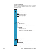
Figure 2-4 illustrates the front panel alarm lights, power supply lights, and reset
button. An alarm source triggers the main alarm light and also one of the
additional six red alarm lights, allowing you to identify or correct alarm
conditions before they affect the operation of the matrix.
Each of the four green power supply lights stays on continuously to show that the
power supplies are receiving sufficient AC current. When one of these lights
switches off, the power supplies need to be replaced or repaired.
Under normal operating conditions, the red front-panel alarm lights stay off,
while the green power supply lights stay on continuously.
The power supplies may need to be adjusted if E-Que or fiber cards are installed.
For details of the adjustments please refer to the system upgrade manual.