
Instruction manual


ECLIPSE OMEGA MATRIX INSTRUCTION MANUAL
2-2
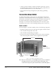
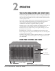
CENTRAL PROCESSOR UNIT (CPU) CARD DESCRIP-
TION
The central processor unit (CPU) card holds the circuitry that allows the system
to connect to, and communicate with, the following interfaces:
•A computer
• External alarms
• Eight general-purpose inputs (GPIs)
• Eight general-purpose outputs (GPOs)
• Two separate local area network (LAN) connections for Ethernet-based
communication with a network
• An external interface that provides additional GPIs and GPOs
In addition, the card’s operational memory holds four complete preassigned
system configurations to access and activate either directly from the CPU card or
from the ECS configuration software.
CREATING AND STORING SYSTEM CONFIGURATIONS
A “configuration” is a complete set of operating parameters for the system which
includes talk and listen paths for each connected intercom panel. Depending on
the interfaces installed, the configuration can also include more sophisticated
features such as paging, call signaling, interrupt foldback (IFB), ISO, groups,
automatic DTMF dialing, routing, and many other features.
When you connect an external computer to the matrix, you can retrieve the
current configuration information stored in the CPU microprocessor’s memory
(using the Eclipse Configuration Software) and display the configuration on the
computer’s screen.
You can then apply the current configuration, modify it, or create a new
configuration with the Eclipse Configuration Software. If you create more than
one configuration, you can store unused configurations on your computer’s hard
disk or on CD-ROM to use later, allowing you to instantly reconfigure your
system as often as you require.
The CPU card itself will store up to four complete configurations in its
operational memory that you can apply either directly from the CPU card or
from the connected computer.
SETTING THE DEFAULT IP ADDRESS
The CPU card LAN ports can be reset to their default IP addresses by pressing
and holding the ‘ENG’ and ‘FULL RESET’ buttons on the CPU front card and
then pressing the ‘RESET’ button at the top and then holding the ‘ENG’ and
‘FULL RESET’ buttons until the card resets. This will reset the LAN1 ethernet
port to the factory default address of 172.16.2.100 and all other ethernet ports to
the 0.0.0.0 (blank) address.
Note: General Purpose
Outputs are also
referred to as “relays.”
Note: If the
configuration does not
remain in memory after
you power off, please
see the first section in
Chapter 3,
“Reconnecting the CPU
Card’s Backup Battery.”