
Instruction manual


ECLIPSE OMEGA MATRIX INSTRUCTION MANUAL
2-1
OPERATION
THE ECLIPSE OMEGA MATRIX AND CIRCUIT CARDS
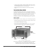
The Eclipse Omega matrix chassis houses the circuit cards, power supplies, and
connectors that form the central hardware of the system. Measuring 19-inches
wide and 6 rack units high (48.3 cm x 26.9 cm), the matrix chassis installs in a
standard equipment rack.
Various types of Eclipse Omega circuit cards perform unique functions. System
cards control overall system operation, port cards control the operation of
connected panels and interfaces and communications cards allow
communication with wireless equipment and fiber optic links.
Two Euro Cassette power supplies provide fail-safe redundancy in the event of a
component failure or an AC circuit outage. Front-panel lights give you
information about the condition of the power supplies, allowing you to take
preventative corrective action.
Each MVX circuit card connects to an individual panel on the back of the
Eclipse Omega matrix. This panel holds the RJ-45 sockets for connecting cable
to intercom panels and interfaces.
The Eclipse Omega matrix is completely modular, allowing you to add or remove
cards, power supplies, and connector panels to meet the operational needs of
your environment.
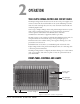
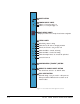
FRONT-PANEL CONTROLS AND LIGHTS
Figure 2-1: Front Panel of Eclipse Omega Matrix
CPU Cards
P1 & P2
Port Cards 1 through 15
Two Euro Cassette
Power Supplies
Power Supply Lights
and Alarm Reset Button
2